
Ford Mustang (1999-2004) Service Manual: Countershaft
Special Tool(s)
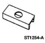 |
Plate, Bearing Oil Seal 205-090 (T75L-1165-B) |
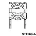 |
Puller, Bearing 205-D064 (D84L-1123-A) |
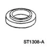 |
Installer, Drive Pinion Bearing Cone 205-004 (T53T-4621-B) |
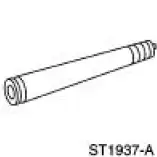 |
Remover/Installer, Bearing Tube 308-025 (T75L-7025-C) |
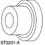 |
Installer, Output Shaft Rear Bearing 308-401 |
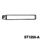 |
Adapter for 303-224 (Handle) 205-153 (T80T-4000-W) |
Disassembly and Assembly
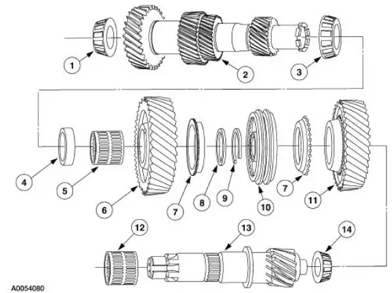
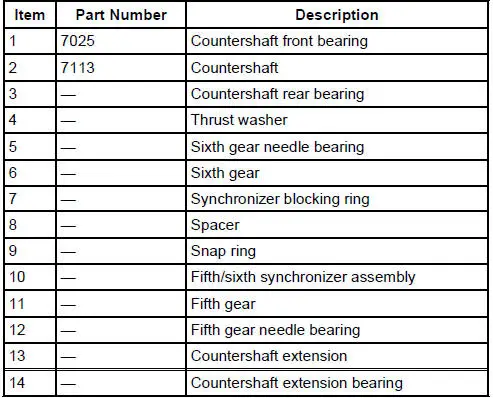
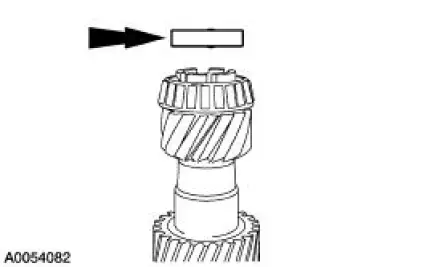
1. Remove the thrust washer.
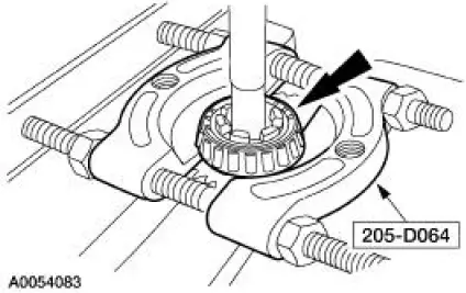
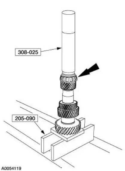
2. Using the special tool and a press, remove the countershaft rear bearing.
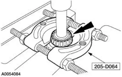
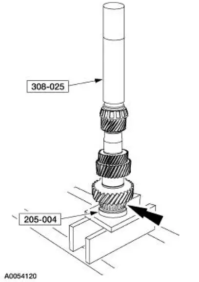
3. Using the special tool and a press, remove the countershaft front bearing.
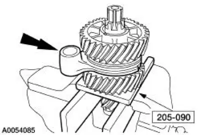
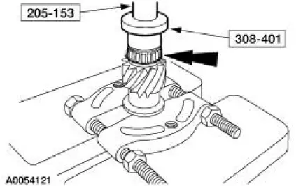
4. Place the special tool in a vise. Position the countershaft extension in the tool with the sixth drive gear facing upward. Remove the fifth/sixth shift fork.
5. Remove the sixth drive gear.
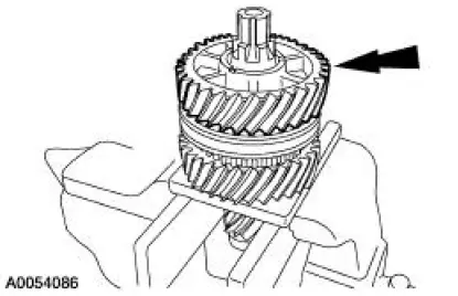
6. Remove the sixth drive gear needle bearing.
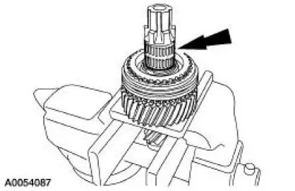
7. Remove the sixth drive gear synchronizer blocking ring.
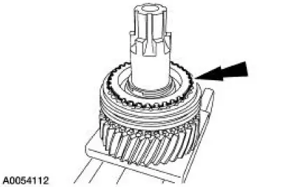
8. Remove and discard the fifth/sixth synchronizer snap ring.
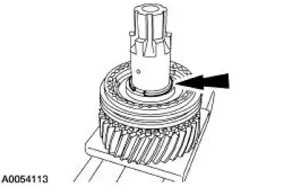
9. Using the special tool, press the fifth/sixth synchronizer and the fifth drive gear off the shaft.
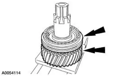
10. Remove the fifth drive gear needle bearing.
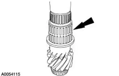
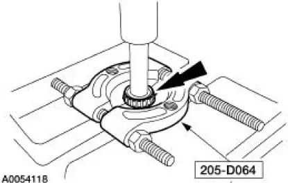
11. Using the special tool, remove the countershaft extension bearing.
12. Inspect the countershaft and countershaft extension.
- Check the shaft surface for wear or damage. Install a new shaft as necessary.
- Check the gear teeth for wear, pitting, scoring, spalling or fractures. Install new components as necessary.
13. Disassemble the fifth/sixth gear synchronizer assembly.
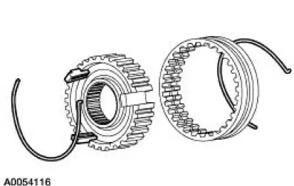
14. Inspect the fifth/sixth synchronizer.
- Check for worn, nicked or broken teeth. Install a new synchronizer as necessary.
- Check keys for wear or distortion. Install a new synchronizer as necessary.
- Check springs for distortion. Install a new synchronizer as necessary.
15. Inspect the fifth/sixth synchronizer blocking rings.
- Check for wear or damage. Install new synchronizer blocking rings as necessary.
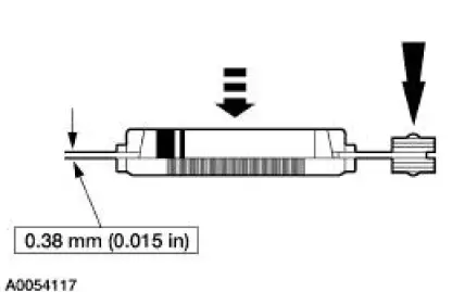
- Check the clearance between the synchronizer blocking ring and the gear.
- Position the blocking ring onto the gear. Make sure the correct blocking ring is measured with the correct gear and that the blocking ring is fully seated on the gear.
- Insert a feeler gauge and measure the clearance, while applying pressure and rotating the blocking ring. The measurement should be the same around the entire circumference. If the clearance is less than 0.38 mm (0.015 in), install new blocking rings.
16. Using the special tools, install the countershaft rear bearing.
17. Using the special tools, install the countershaft front bearing.
18. Using the special tools, install the countershaft extension bearing.
19. To assemble, reverse the disassembly procedure.
- Assemble the synchronizer assembly before installing.
 Assembly
1. Lubricate all components with the recommended transmission fluid when
reassembling.
2. Using the special tools, press the output shaft front bearing on the output
shaft.
3. Install the third g ...
 Synchronizers
Disassembly and Assembly
NOTE: This procedure applies to all synchronizer assemblies.
1. NOTE: Synchronizer components are not interchangeable. During
disassembly, mark each
individual synchronizer f ...
Other materials:
Stabilizer Bar - Cobra
Removal
CAUTION: Suspension fasteners are critical parts because they affect
performance of vital
components and systems and their failure can result in major service expense. A
new part with
the same part number must be installed if installation becomes nec ...
Side airbags
WARNING: Do not place objects or mount equipment on or near
the airbag cover, on the side of the seat backs (of the front seats),
or in front seat areas that may come into contact with a deploying airbag.
Failure to follow these instructions may increase the ...
Supercharger Belt
Removal and Installation
1. Remove the supercharger drive belt cover.
2. Rotate the supercharger belt tensioner clockwise and remove the
supercharger belt.
3. To install, reverse the removal procedure. ...
