Ford Mustang (1999-2004) Service Manual: Assembly
1. Lubricate all components with the recommended transmission fluid when reassembling.
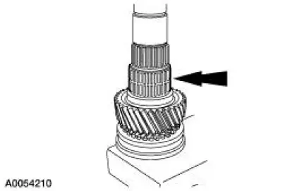
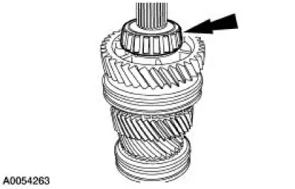
2. Using the special tools, press the output shaft front bearing on the output shaft.
3. Install the third gear bearing.
- Apply petroleum jelly to the bearing.
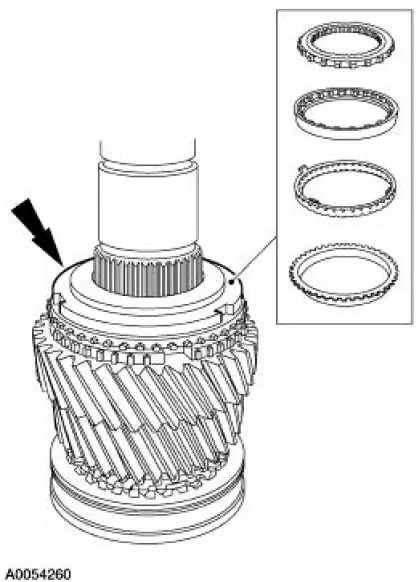
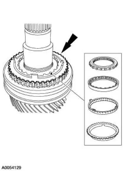
4. Install third gear, the third gear synchronizer blocking ring and the third/fourth gear synchronizer assembly. Position the output shaft with the output end facing upward. Using the special tool, press the third/fourth gear synchronizer assembly into place.
- Install the synchronizer body with the groove facing third gear.
- Stop press operation before keys engage the blocking ring slots. Lift and rotate the third gear and the blocking ring until the keys are seated in the blocking ring.
5. Install a new snap ring.
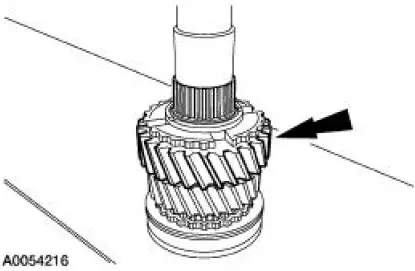
6. Install the second gear needle bearing.
- Apply petroleum jelly to the bearing.
7. Install second gear.
8. Install the second gear synchronizer thrust washer, the inner cone, the friction cone and the second gear synchronizer blocking ring.
- Align the blocking ring tabs with the second gear slots.
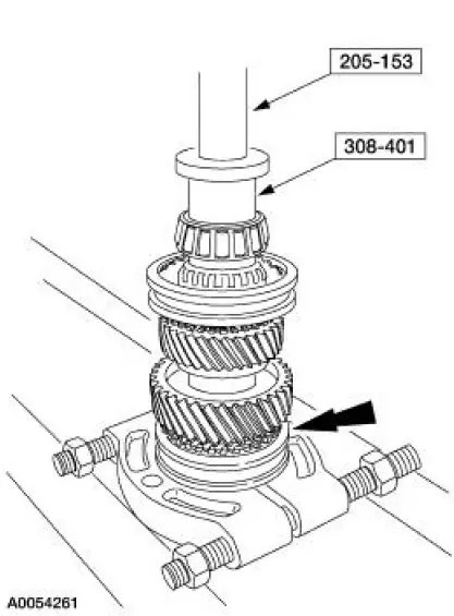
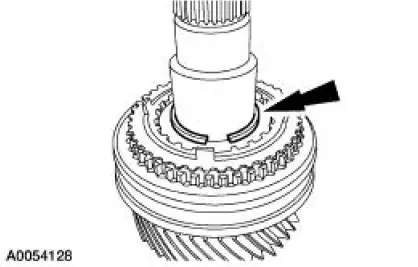
9. Install the first/second gear synchronizer assembly. Position the output shaft with the output end facing downward. Using the special tools, press the first/second gear synchronizer assembly into place.
- Install the synchronizer with the groove on the sleeve facing first gear.
- Stop press operation before keys engage the blocking ring slots. Lift and rotate the second gear and the blocking ring until the keys are seated in the blocking ring.
10. Install the first gear synchronizer thrust washer, the inner cone, the friction cone and the first gear synchronizer blocking ring.
11. Install a new snap ring.
12. Install the first gear needle bearing.
- Apply petroleum jelly to the bearing.
13. Install first gear.
- Rotate the gear to align the gear slots with the inner cone tabs.
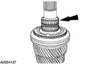
14. Install a new rear output shaft bearing.
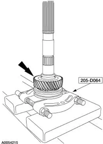
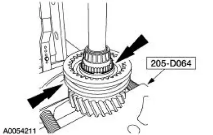
15. Using the special tools, install the fifth driven gear.
 Disassembly
1. CAUTION: Hand tighten the special tool to prevent gear damage.
CAUTION: Support the output shaft while using the press to prevent
damage to the
shaft or gears.
Using the special tool and ...
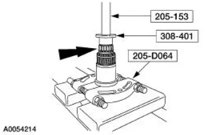
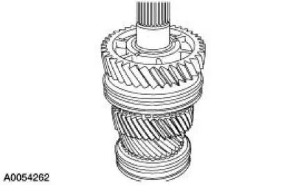
 Countershaft
Special Tool(s)
Plate, Bearing Oil Seal
205-090 (T75L-1165-B)
Puller, Bearing
205-D064 (D84L-1123-A)
Installer, Drive Pinion Bearing
Cone
205-004 (T53T-4621- ...
Other materials:
Diagnostic Instructions - Air Bag Supplemental Restraint
System (SRS)
Special Tool(s)
Worldwide Diagnostic System
(WDS)
418-F224,
New Generation STAR (NGS)
Tester
418-F052, or equivalent scan
tool
The symptom chart can be used to help locate the air bag supplemental
restraint system (SRS)
concerns if n ...
Instrument Cluster (Diagnosis and Testing)
Refer to Wiring Diagrams Cell 60 , Instrument Cluster for schematic and
connector information.
Special Tool(s)
Worldwide Diagnostic System
(WDS)
418-F224,
New Generation STAR (NGS)
Tester
418-F052, or equivalent
diagnostic tool
...
Principles of operation
MyKey allows you to program keys with restricted driving modes to
promote good driving habits. You can use all but one of the keys
programmed to your vehicle with these restricted modes.
Any keys that have not been programmed are referred to as
administrator ...
