Ford Mustang (1999-2004) Service Manual: Digital Transmission Range (TR) Sensor
Special Tool(s)
|
|
Alignment Gauge, TR Sensor 307-351 (T97L-70010-A) |
Removal
1. Disconnect the battery ground cable. For additional information, refer to Section.
2. Raise and support the vehicle. For additional information, refer to Section.
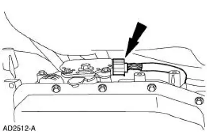
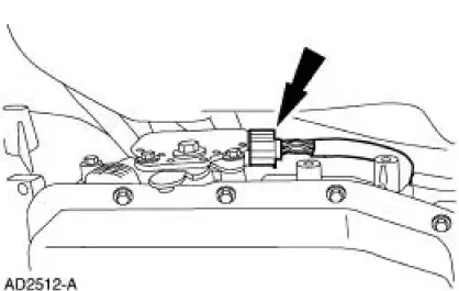
3. Disconnect the connector.
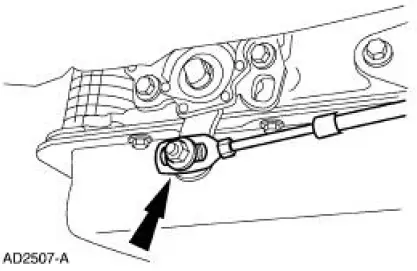
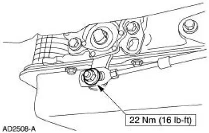
4. Disconnect the manual lever shift control cable.
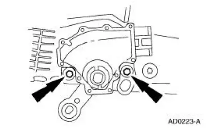
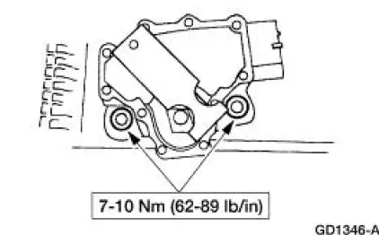
5. Remove the digital TR bolts and the TR sensor.

Installation
1. Install the digital TR sensor and loosely install the bolts.
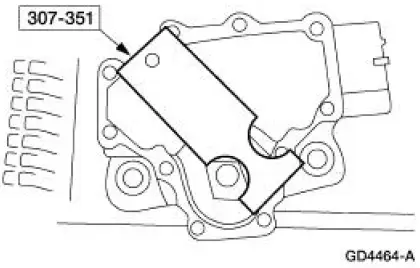
2. NOTE: The tool is designed to fit snugly.
NOTE: Manual shift lever shaft must be in the neutral position.
Using the special tool, align the digital TR sensor slots.
3. Tighten the bolts.
4. With the manual lever in overdrive connect the shift lever control cable.
5. Install the digital TR sensor electrical connector.
6. Lower the vehicle.
7. NOTE: When the battery is disconnected and reconnected, some abnormal driving symptoms may occur while the vehicle relearns its adaptive strategy. The vehicle may need to be driven 16 km (10 miles) or more to relearn the strategy.
Connect the battery ground cable.
 Manual Control Lever Shaft and Seal
Special Tool(s)
Installer, Shift Shaft Fluid Seal
307-050 (T74P-77498-A)
Alignment Gauge, TR Sensor
307-351 (T97L-70010-A)
Removal
1. Drain the transmission fluid and re ...
 Reverse Servo Assembly
Special Tool(s)
Dial Indicator Gauge with
Holding Fixture
100-002 (TOOL-4201-C)
Remover/Installer, Servo
Piston
307-251 (T92P-70023-A)
Installer, Servo Pisto ...
Other materials:
Brake Booster - Vacuum (Description and Operation)
Power Brake Booster
The vacuum type power brake booster (2005):
is a dual diaphragm, vacuum assisted power brake booster
reduces brake pedal force and travel distance.
is located on the LH side of the bulkhead in the engine compartment,
be ...
Removal
NOTE: The convertible top hydraulic components are removed from the vehicle
as an assembly. The
hydraulic components are individually repaired and the system must be bled
before being installed into
the vehicle.
Hydraulic system
1. Unlatch the convertible to ...
Installation
1. Align the blend door driver to the full heat position.
2. Place the temperature control knob in the full WARM position.
3. Attach the cable drive to the control head.
4. Rotate the knob back and forth from full WARM to full COOL.
5. Check the cable ...
