Ford Mustang (1999-2004) Service Manual: Reverse Servo Assembly
Special Tool(s)
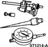 |
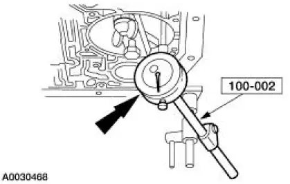
Dial Indicator Gauge with Holding Fixture 100-002 (TOOL-4201-C) |
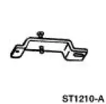 |
Remover/Installer, Servo Piston 307-251 (T92P-70023-A) |
 |
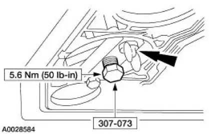
Installer, Servo Piston 307-073 (T80L-77030-A) |
Removal
1. Remove the main control valve body. For additional information, refer to Main Control Valve Body in this section.
2. Using the special tool, remove the reverse band servo retaining ring.
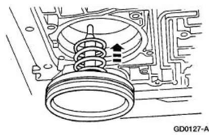
1. Compress the servo spring.
2. Remove the reverse band servo retaining ring.
3. Remove the reverse servo assembly.
1. Remove the reverse band servo cover.
2. Remove the reverse band servo piston and rod.
3. Remove the reverse band servo spring.
Installation
NOTE: This is not an ordinary installation procedure and does not compensate for band wear.
1. NOTE: Lubricate the reverse piston seal to facilitate assembly and prevent damage to the seal.
Install the reverse servo return spring and piston.
- Do not install the piston cover.
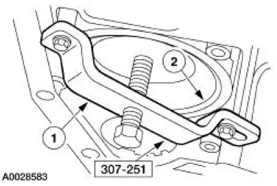
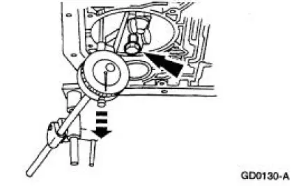
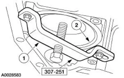
2. Install the special tool and tighten the band apply bolt.
3. Attach the special tool to the transmission.
- Position the indicator stem on the flat portion of the reverse servo piston and zero the dial indicator.
4. Loosen the bolt until the piston stops against the tool.
5. Verify that the amount of piston travel on the dial indicator is within specification.
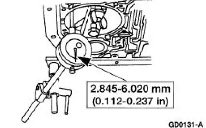
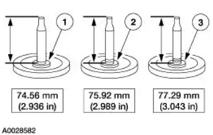
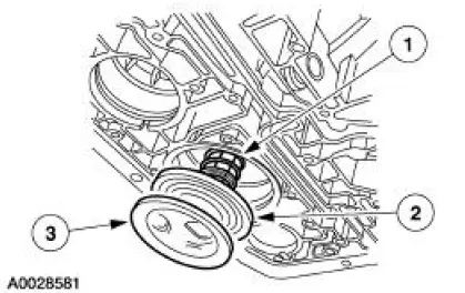
6. If piston travel is not within specification, select and install the correct servo piston assembly to bring the servo piston travel within specification.
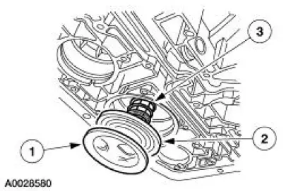
1. One groove
2. Two groove
3. Three groove
7. Remove the dial indicator and servo selection tool.
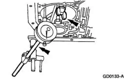
8. Install the correct reverse servo assembly.
1. Install the reverse band servo spring.
2. Install the reverse band servo piston and rod.
3. Install the reverse band servo cover.
9. Using the special tool, install the reverse servo retaining ring.
1. Compress the servo spring.
2. Install the reverse band servo retaining ring.
10. Install the main control valve body. For additional information, refer to Main Control Valve Body in this section.
 Digital Transmission Range (TR) Sensor
Special Tool(s)
Alignment Gauge, TR Sensor
307-351 (T97L-70010-A)
Removal
1. Disconnect the battery ground cable. For additional information, refer
to Section.
2. Raise and suppor ...
 Overdrive Servo
Special Tool(s)
Remover/Installer, Servo
Piston
307-251 (T92P-70023-A)
Removal
1. Remove the main control valve body. For additional information, refer
to Main Control Valve
Body ...
Other materials:
Installation
1. Install the bearing.
1. Position the knuckle on the press.
2. Using the appropriate step plate adapter, press the bearing into the
knuckle until the
bearing clears the snap ring groove and bottoms out in the bore.
2. Install the snap ring.
3. CA ...
Pinpoint Test L: B1892 - Air Bag Tone Warning Indicator Circuit Shorted to
Ground or Open
Normal Operation
The restraints control module (RCM) monitors its connection to the
generic electronic module (GEM) at
C201e pin 10. This connection is used to signal a chime if the air bag
indicator is inoperative and
another SRS fault exists. If the R ...
Autolamps
WARNING: In severe weather conditions, it may be necessary to
switch your headlamps on manually.
Note: If the vehicle is equipped with autolamps, it will have the
windshield wiper rainlamp feature. When the windshield wipers are
turned to low- or high-speed wi ...
