Ford Mustang (1999-2004) Service Manual: Manual Control Lever Shaft and Seal
Special Tool(s)
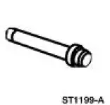 |
Installer, Shift Shaft Fluid Seal 307-050 (T74P-77498-A) |
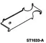 |
Alignment Gauge, TR Sensor 307-351 (T97L-70010-A) |
Removal
1. Drain the transmission fluid and remove the fluid pan and filter. For additional information, refer to Fluid Pan, Gasket and Filter in this section.
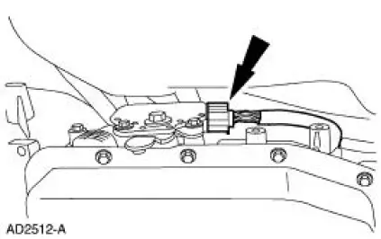
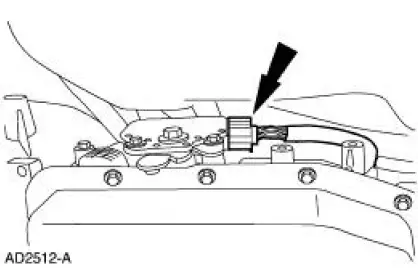
2. Disconnect the digital transmission range (TR) sensor electrical connector.
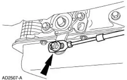
3. Disconnect the transmission shift linkage.
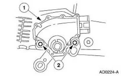
4. Remove the digital TR sensor.
- Remove the bolts.
- Remove the digital TR sensor.
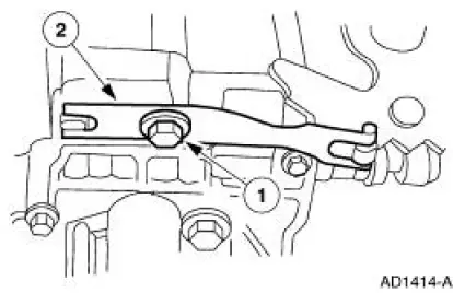
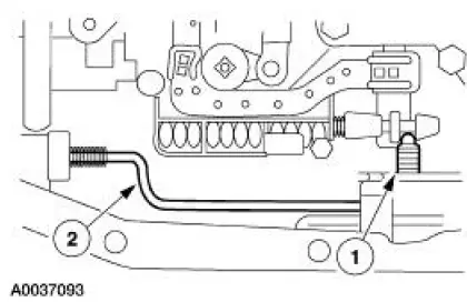
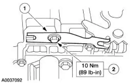
5. Remove the manual control valve detent lever spring.
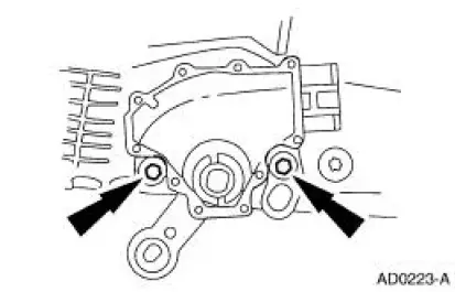
1. Remove the bolt.
2. Remove the manual control valve detent lever spring.
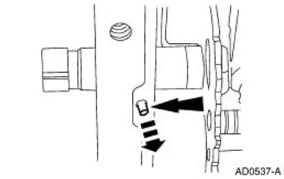
6. NOTE: Use a shop cloth to protect the transmission case surface.
Remove the manual lever shaft retaining pin.
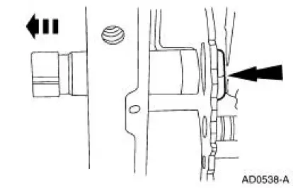
7. Remove the nut and slide the manual control lever shaft out of the case.
8. Remove the parking lever actuating rod.
1. Remove the manual valve detent lever.
2. Remove the parking lever actuating rod.
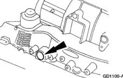
9. CAUTION: Use care not to damage the manual control lever shaft bore. New seal may leak due to damage to the bore.
Remove the manual control lever shaft seal.
Installation
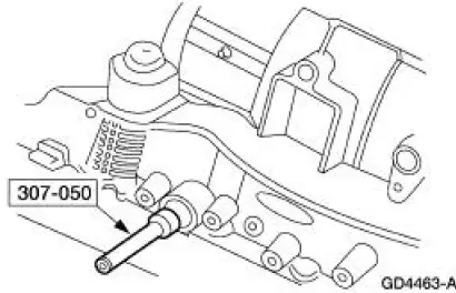
1. Using the special tool, install the manual control lever seal.
2. Install the parking lever actuating rod.
1. Install the parking lever actuating rod.
2. Install the manual valve detent lever.

3. Install the manual control lever shaft.
1. Install the manual control lever shaft.
2. Install the nut.
3. Install the manual lever shaft retaining pin.
4. Install the manual valve detent lever spring.
1. Position the manual valve detent lever spring.
2. Install the bolt.
5. Install the digital TR sensor.
1. Install the digital TR sensor.
2. Loosely install the bolts.
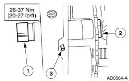
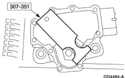
6. NOTE: The tool is designed to fit snug.
NOTE: Manual shift lever shaft must be in the neutral position.
Using the special tools, align the digital TR sensor slots.
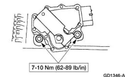
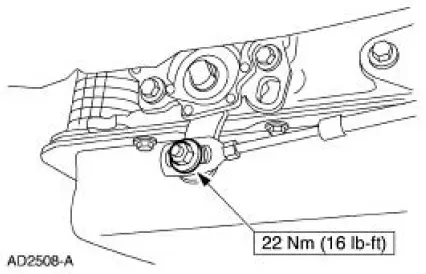
7. Tighten the bolts.
8. With manual lever in overdrive, connect the shift control cable.
9. Install the digital TR sensor electrical connector.
10. Install the filter and transmission fluid pan. For additional information, refer to Fluid Pan, Gasket and Filter in this section.
 Electronic Pressure Control (EPC) Solenoid
Special Tool(s)
Gauge, Transmission Solenoid
Connectors
307-426
Removal
1. Remove the manual control lever. For additional information, refer to
Manual Control Lever
Shaft and Se ...
 Digital Transmission Range (TR) Sensor
Special Tool(s)
Alignment Gauge, TR Sensor
307-351 (T97L-70010-A)
Removal
1. Disconnect the battery ground cable. For additional information, refer
to Section.
2. Raise and suppor ...
Other materials:
Output Shaft
Special Tool(s)
Pinion Bearing Cone Remove
205-D002 (D79L-4621-A) or
Equivalent
Spiral Snap Ring Replacer
308-096 (T85P-7025-A)
Disassembly
1. Using the special tool and a press, remove the third/fourth gear
synchronizer asse ...
Bar - Stabilizer
Removal
CAUTION: Suspension fasteners are critical parts because they affect
performance of vital
components and systems and their failure can result in major service expense. A
new part with
the same part number or an equivalent part must be installed, if i ...
Engine Component View
Cylinder Heads and Valve Train Components
Engine Front Cover Components
Engine Components
Cylinder Block and Lower End Components
Engine (DIAGNOSIS AND TESTING)
Refer to Section for basic mechanical concerns or refer ...
