Ford Mustang (1999-2004) Service Manual: Transmission (Disassembly)
Special Tool(s)
|
|
Bearing Puller 205-D064 (D84L-1123-A) or Equivalent |
|
|
Front Hub Tool 204-069 (T81P-1104-C) |
|
|
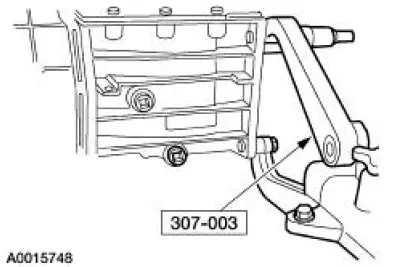
Holding Fixture 307-003 (T57L-500-B) |
|
|
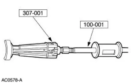
Impact Slide Hammer 100-001 (T50T-100-A) |
|
|
Puller 307-001 (TOOL-1175-AC) or Equivalent |
|
|
Staking Punch 308-056 (T77J-7025-F) |
1. Remove the clutch release hub and bearing and the clutch release lever. For additional information, refer to Section .
2. WARNING: Make sure protective eyewear is in place.
Clean the transmission exterior with solvent and dry with compressed air. During disassembly, clean all components with solvent and dry with compressed air.
3. Attach the transmission to the special tool.
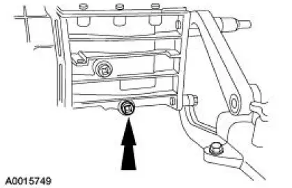
4. NOTE: Position a drain pan under the transmission.
Remove the case plug.
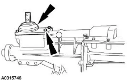
5. NOTE: Position the gearshift lever in NEUTRAL.
Remove the bolts and the gearshift lever.
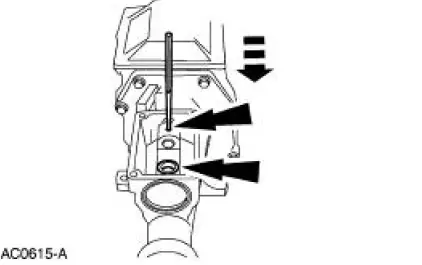
6. CAUTION: Do not attempt to remove the gearshift offset lever with the extension housing bolted in place. A lug, located on the bottom of the gearshift offset lever, meshes with the detent plate preventing enough rearward movement of the gearshift offset lever to allow removal.
Remove the split pin and the gearshift shaft bushing.
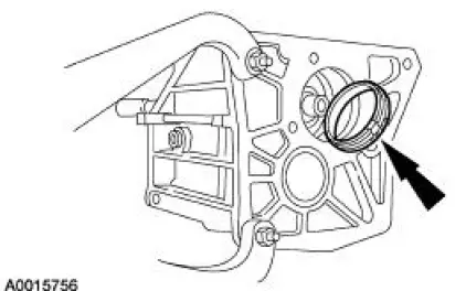
7. Using the special tools, remove the extension housing fluid seal.
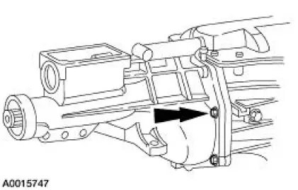
8. Remove the seven bolts and the identification tag.
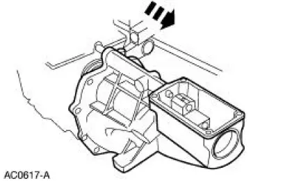
9. CAUTION: The gearshift offset lever is under spring pressure.
While applying downward pressure on the gearshift offset lever, remove the extension housing and the gearshift offset lever as an assembly.
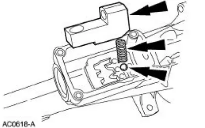
10. Remove the gearshift offset lever, the split pin, the shifter detent spring, and the detent ball.
11. Remove the bolts.
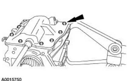
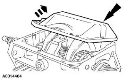
12. Remove the case cover.
- Lift the case cover and slide it toward the filler plug side of the case to clear the reverse gearshift lever.
13. CAUTION: Support the reverse gear shift rail (7240) with a block of wood.
Remove the split pin.
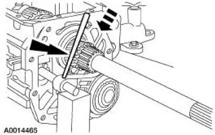
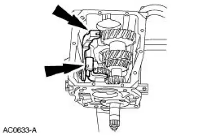
14. Remove the fifth speed synchronizer retaining snap ring, the thrust washer (7G042), the reverse brake ring (7M000), and the synchronizer blocking ring (7107).
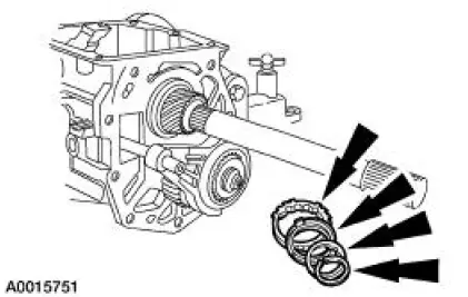
15. Remove the fifth speed cluster gear (7144), the synchronizer blocking ring (7107), the synchronizer assembly (7124), and the fifth gear shifter fork (7230) as an assembly.
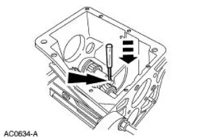
16. Remove the reverse gearshift lever retaining clip.
17. NOTE: Do not remove the reverse gearshift lever (7K002) at this time.
Using a TORX bit driver, remove the shift lever reverse pin (7K024).
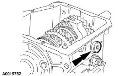
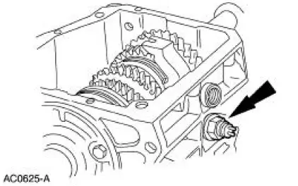
18. Remove the reversing lamp switch (15520).
19. Remove the reverse gear shift rail.
1. Rotate the reverse gear shift rail clockwise to disengage the ball stud from the reverse gearshift lever.
2. Pull the reverse gear shift rail rearward slightly.
3. Rotate the reverse gear shift rail counterclockwise to align the ball stud with the slot in the case and remove the reverse gear shift rail.
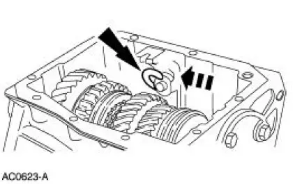
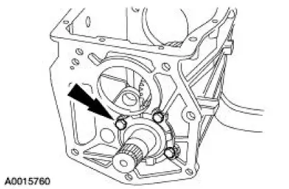
20. Remove the snap ring and the output shaft speed wheel (7H150).
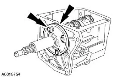
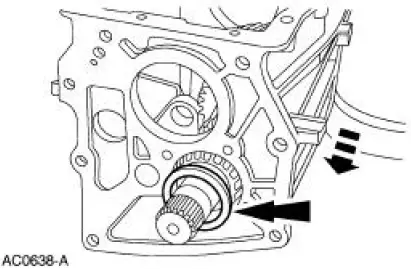
21. Remove the four bolts and the input shaft bearing retainer (7050).
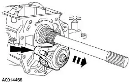
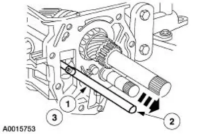
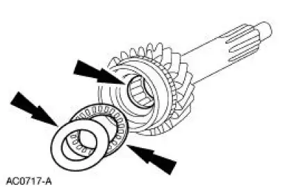
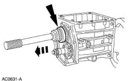
22. CAUTION: Do not drop the 15 roller bearings (7118), the input shaft bearing spacer (7L357), the thrust bearing (7D234), and the thrust washer (7D235) from the rear of the input shaft (7017).
Remove the input shaft.
- Rotate the input shaft until the flat on the fourth gear clutching teeth aligns with the countershaft cluster gear (7113).
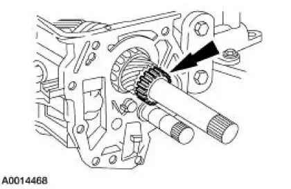
23. Remove the thrust washer, the thrust bearing, the input shaft bearing spacer, and the 15 roller bearings.
24. Remove the fourth speed synchronizer blocking ring (7107).
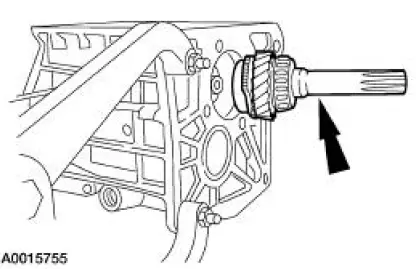
25. NOTE: If the output shaft rear bearing cup sticks, it is misaligned in the case bore. To free the output shaft rear bearing cup, work the output shaft assembly (7061) back and forth in the case (7005).
Remove the output shaft rear bearing cup.
26. Remove the output shaft assembly.
27. NOTE: Observe the location of the reverse gearshift lever, the reverse shift fork (7230), and the reverse positioning spring (7E485).
NOTE: Observe the rotation action of the reverse positioning spring.
Remove the reverse gearshift lever, the reverse shift fork, and the reverse positioning spring as an assembly.
- Hold the reverse gearshift lever and lift it upward as straight up as possible to remove the assembly.
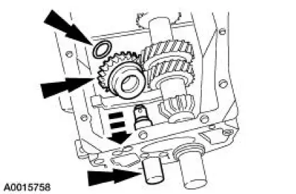
28. Remove the pin.
29. Remove the reverse idler gear shaft (7140), the reverse idler gear and bushing (7141), and the reverse gear overtravel stop (7E397).
30. Using the special tool, flatten the tabs on the countershaft rear bearing retainer (7195).
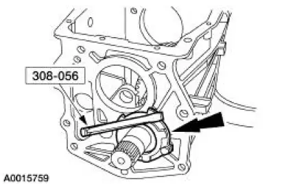
31. Remove the four bolts, the countershaft rear bearing retainer, and the shim (7L172).
32. NOTE: If the bearing race sticks in the case, it is misaligned in the case bore. To free the race, work the countershaft cluster gear back and forth.
Remove the bearing race.
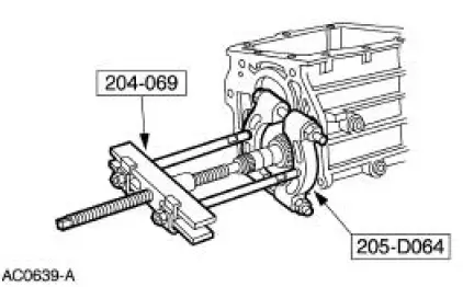
33. Using the special tools, remove the rear countershaft bearing assembly (7F431).
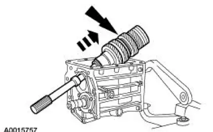
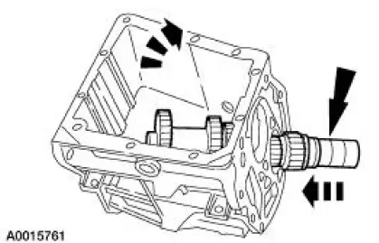
34. Move the countershaft cluster gear rearward through the bearing bore. Tilt the assembly upward and remove it from the case.
 Transmission (Removal)
1. Disconnect the battery ground cable. For additional information, refer
to Section.
2. Lift up on the clutch pedal and secure it in place.
3. Remove the gearshift lever knob (7213).
4. Remov ...
 Selector Plate
...
Other materials:
Exhaust System (Description and Operation)
WARNING: The normal operating temperature of the exhaust system is very
high. Never
attempt to repair any part of the system until it has cooled. Be especially
careful when working
around the three way catalytic converter. The temperature of the three way
c ...
Compressor Manifold and Tube Assembly - 4.6L
Material
Item
Specification
PAG Refrigerant Compressor
Oil (R-134a Systems)
F7AZ-19589-DA (Motorcraft YN-
12-C)
WSH-M1C231-
B
Removal and Installation
NOTE: Installation of a new suction accumulator is not required when
repairing the ...
Spring Lock Couplings
Special Tool(s)
Disconnect Tool, Spring Lock
Coupling (3/8 inch yellow)
310-D004 (D87L-9280-A) or
equivalent
Disconnect Tool, Spring Lock
Coupling (1/2 inch green)
310-D005 (D87L-9280-B) or
equivalent
Material
Item
...
