Ford Mustang (1999-2004) Service Manual: Disc and Pressure Plate - 4.6L (4V) Engine
Special Tool(s)
 |
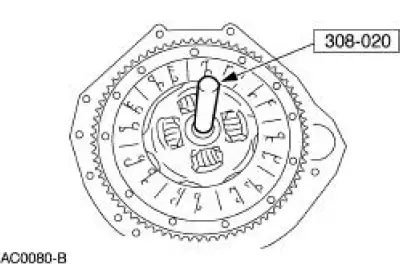
Clutch Aligner 308-020 (T74P-7137-K) |
Material
| Item | Specification |
| Premium Long Life Grease XG-1-C | ESA-M1C75-B |
1. Disconnect the battery ground cable. For additional information, refer to Section.
2. Remove the transmission. For additional information, refer to Section.
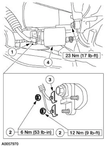
3. Remove the starter.
1. Remove the terminal cap.
2. Remove the nuts.
3. Remove the wires and position them aside.
4. Remove the two bolts and the starter.
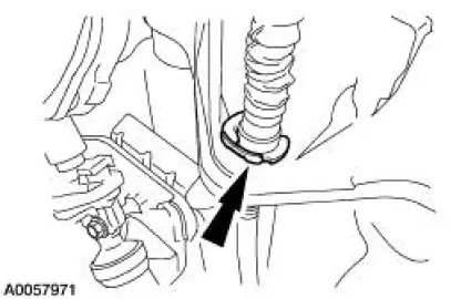
4. Remove the clutch cable clip, then pull the cable through the clutch housing.
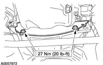
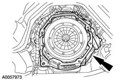
5. Remove the two bolts and the inspection cover.
6. Remove the seven bolts and the clutch housing.
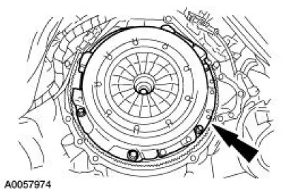
7. CAUTION: Loosen the bolts evenly to prevent damage to the pressure plate.
NOTE: If the pressure plate is to be reused, index-mark the pressure plate to the flywheel.
Remove the six bolts and the pressure plate and disc.
Installation
1. NOTE: Clean the clutch pressure plate and flywheel with a commercial alcohol-based solvent so surfaces are free from oil film. Do not use cleaners with a petroleum base.
NOTE: Before installing the transmission, the ball stud, the clutch release lever and the input shaft must be cleaned and lubricated with grease.
To install, reverse the removal procedure.
- Using the special tool, align the clutch disc and pressure plate to the flywheel.
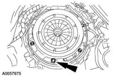
2. Tighten the pressure plate bolts in two stages.
- Stage 1: Tighten the bolts to 45 Nm (33 lb-ft).
- Stage 2: Tighten the bolts an additional 60 degrees.
 Disc and Pressure Plate - 3.8L and 4.6L (2V) Engines
Special Tool(s)
Clutch Aligner
308-020 (T74P-7137-K)
Material
Item
Specification
Premium Long Life Grease
XG-1-C
ESA-M1C75-B
1. Remove the transmission.
2. CAUTION ...
 Pilot Bearing
Special Tool(s)
Puller with Slide Hammer
308-001 (T58L-101-B)
1. Remove the clutch disc and the clutch pressure plate. For additional
information, refer to Disc
and Pressure Plate-3.8 ...
Other materials:
Shift Point Road Test
This test verifies that the shift control system is operating
correctly.
1. Bring engine and transmission up to normal operating temperature.
2. Operate vehicle with transmission range selector lever in (D)
position.
3. NOTE: Shift speed ranges a ...
Electronic Pressure Control (EPC) Solenoid
Special Tool(s)
Gauge, Transmission Solenoid
Connectors
307-426
Removal
1. Remove the manual control lever. For additional information, refer to
Manual Control Lever
Shaft and Seal in this section.
2. CAUTION: Do not pull on the molded ...
Wheel Studs
Removal
1. Remove the wheel hub (1104). For additional information, refer to Wheel
Hub and Bearing in
this section.
2. Using a press, remove the wheel stud (1107) from the wheel hub.
Installation
1. Using a press, install a new wheel stud.
2. Install the w ...
