Ford Mustang (1999-2004) Service Manual: Engine (Installation)
Special Tool(s)
|
|
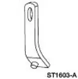
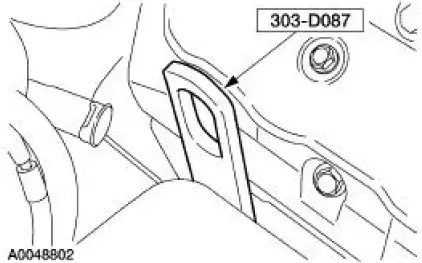
Lifting Bracket, Engine 303-D087 (D93P-6001-A1) |
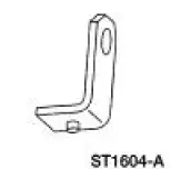 |
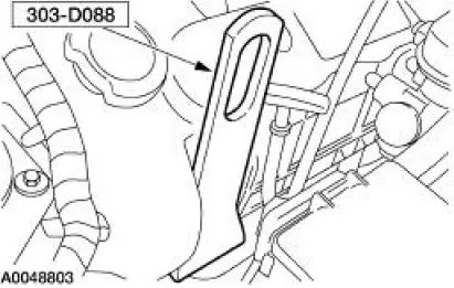
Lifting Bracket, Engine 303-D088 (D93P-6001-A2) |
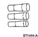 |
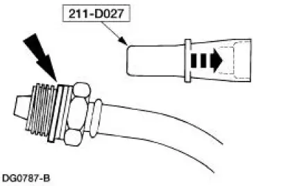
Installer Set, Teflon Seal 211-D027 (D90P-3517A) or equivalent |
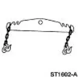 |
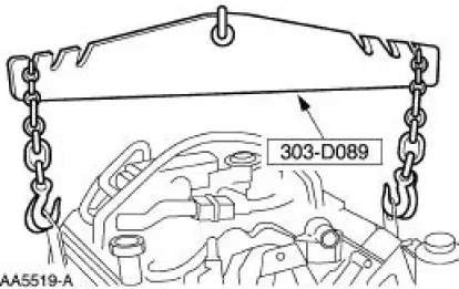
Spreader Bar 303-D089 (D93P-6001-A3) or equivalent |
Material
| Item | Specification |
| Super Premium SAE 5W-20 Engine Oil XO-5W20-QSP or equivalent | WSS-M2C153- H |
| Motorcraft Premium Gold Engine Coolant VC-7-A (in Oregon VC-7-B) (yellow color) | WSS-M97B51- A1 |
| Threadlock and Sealer E0AZ-19554-AA | WSK-M2G351- A5 |
Installation
All vehicles
1. Install the engine in the vehicle and remove the floor crane and the spreader bar.
Manual transmission vehicles
2. Install the clutch cable and retaining screws.
All vehicles
3. Raise and support the vehicle. For additional information, refer to Section.
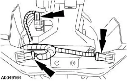
4. Connect the transmission wiring harness.
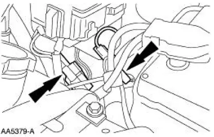
1. Connect the RH oxygen sensor connector retainer.
2. Connect the transmission harness electrical connector.
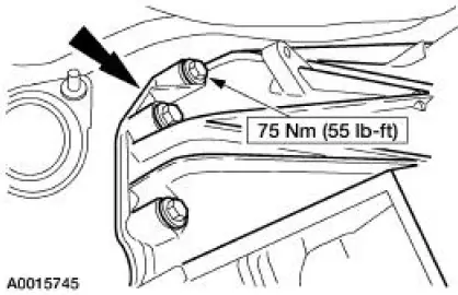
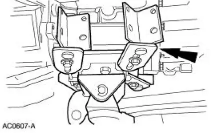
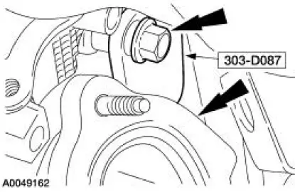
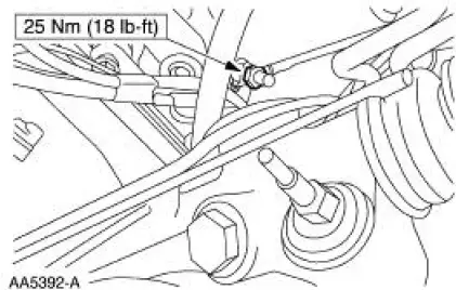
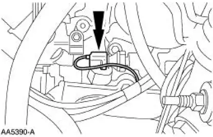
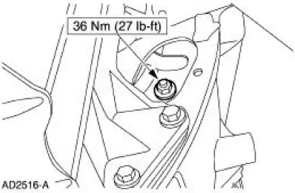
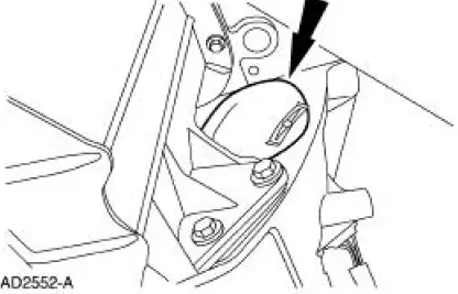
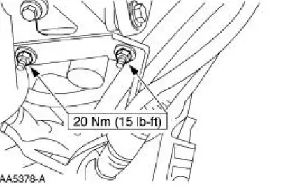
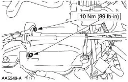
5. NOTE: RH side shown, LH side similar.
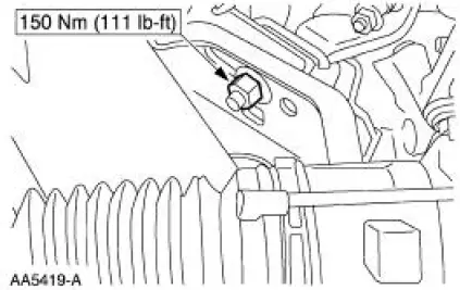
Install the LH and RH engine mount nuts.
Manual transmission vehicles
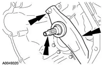
6. Lubricate the ball stud, clutch release lever and the input shaft with clean engine oil.
All vehicles
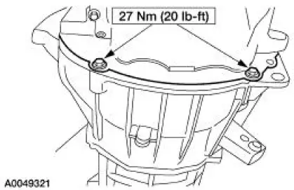
7. Raise the transmission and install the seven bolts.
8. Install the bolts.
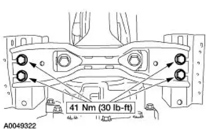
9. Install the transmission crossmember and the bolts.
10. Remove the transmission jack.
Manual transmission vehicles
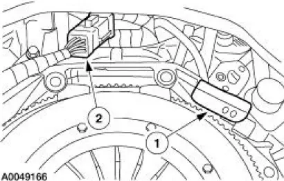
11. Install the clutch cable and the clutch cable retainer.
12. Attach the clutch release cable to the clutch release fork.
13. Install the clutch release lever cover and bolt.
All vehicles
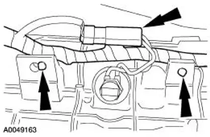
14. Connect the output shaft speed (OSS) sensor electrical connector and attach the left and right oxygen sensor electrical connectors to the crossmember.
15. Connect the reversing lamp switch electrical connector and the wiring harness to the transmission.
16. Remove the two bolts from the RH lifting bracket.
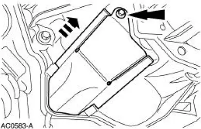
17. Install the degas bottle support bracket.
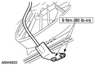
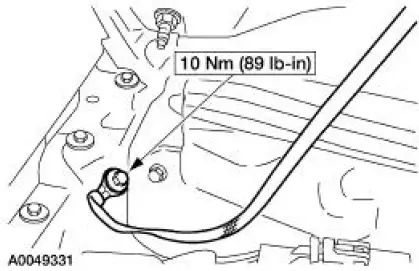
18. Connect the engine ground strap to the frame.
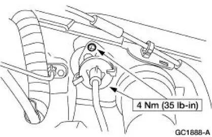
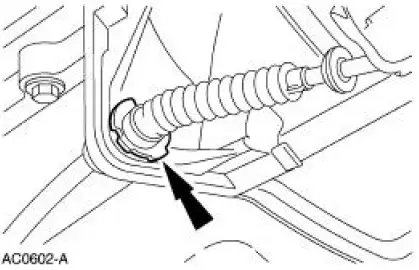
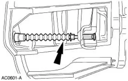
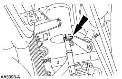
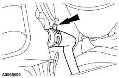
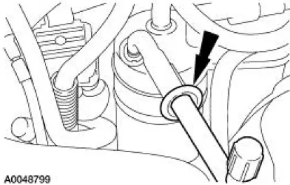
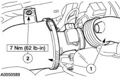
19. Using the special tool, install a new seal ring.
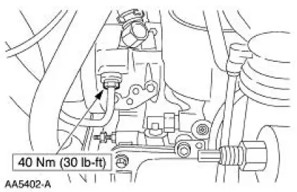
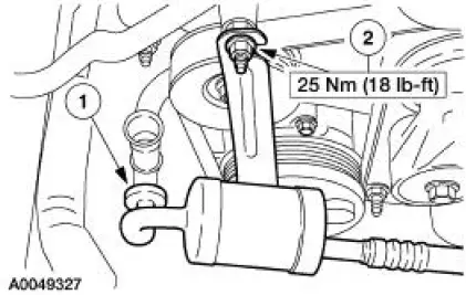
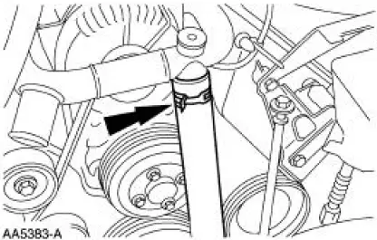
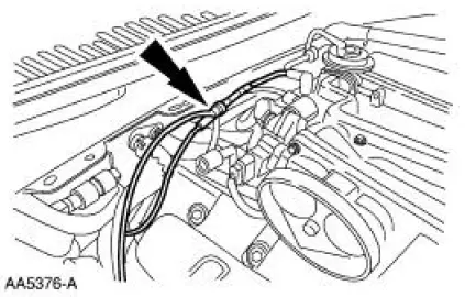
20. Install the high pressure power steering hose to the pump.
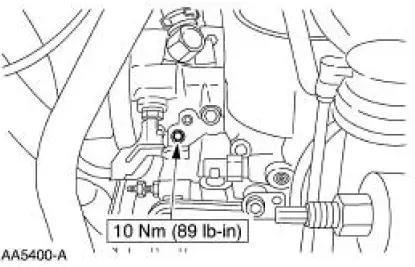
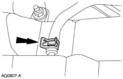
21. Position the clip and install the bolt.
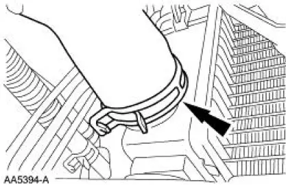
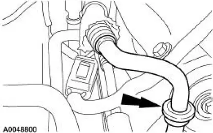
22. Connect the hose to the power steering reservoir.
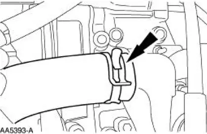
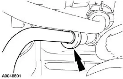
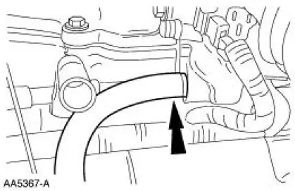
23. Connect the lower radiator hose.
24. Connect the hose to the oil filter adapter.
25. Install the ground cable.
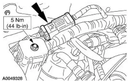
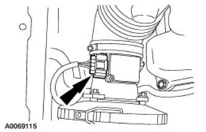
26. Connect the oil pressure sender.
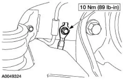
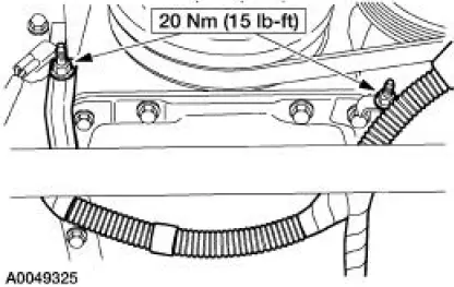
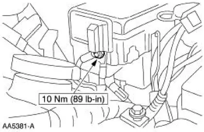
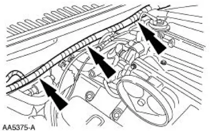
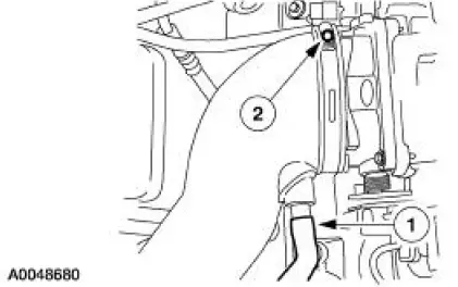
27. Position the wiring harness and install the two nuts.
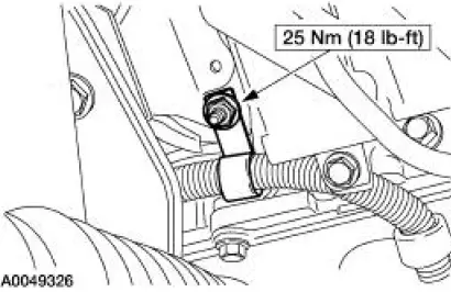
28. Position the wiring harness bracket and install the nut.
29. Position the starter and install the bolts.
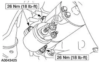
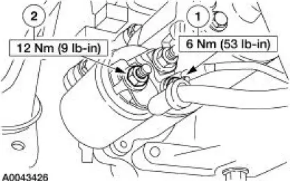
30. Install the starter wires.
1. Position the solenoid wire and install the nut.
2. Position the battery cable and install the nut.
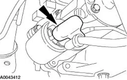
31. Install the cap.
Automatic transmission vehicles
32. Install the torque converter nuts.
33. Install the flywheel inspection cover.
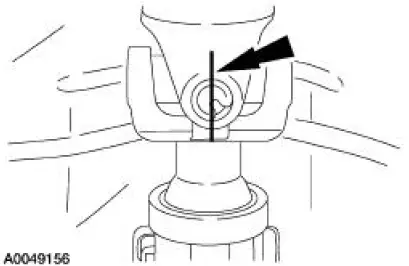
34. Install the driveshaft onto the transmission output shaft, aligning the index-mark in the six o'clock position.
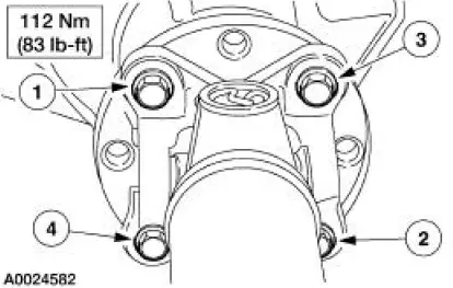
35. CAUTION: Use new bolts to install the driveshaft. If new bolts are not available, apply threadlock to the threads of the original bolts.
CAUTION: The driveshaft centering socket yoke fits tightly on the rear axle pinion flange pilot. To make sure the yoke seats squarely on the flange, tighten the bolts evenly in the sequence shown.
NOTE: Align the marks made on the flange and driveshaft during removal.
Position the driveshaft and install the driveshaft-to-pinion flange bolts in the sequence shown.
36. Install the A/C muffler.
1. Connect the A/C tube and position the A/C muffler.
2. Install the bracket nut.
37. Install the dual converter H-pipe. For additional information, refer to Section.
38. Lower the vehicle.
39. Install the shifter.
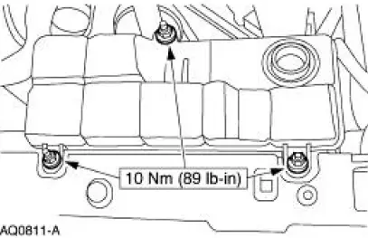
40. Install the degas bottle.
41. Connect the degas bottle return hose.
42. Connect the radiator vent hose to the degas bottle.
43. Remove the LH lifting bracket.
44. Remove the RH lifting bracket.
45. Connect the A/C tube.
46. Connect the A/C suction tube to the manifold tube.
47. Connect the A/C suction tube to the accumulator.
48. Connect the hose to the bypass tube.
49. Connect the cables.
50. Connect the connectors.
51. Position the wiring support bracket and install the nuts.
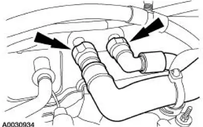
52. Connect the heater hoses.
53. Connect the vacuum hoses.
54. Connect the fuel charging wiring harness.
55. Connect the 16-pin and the 42-pin connectors.
56. Connect the evaporative emissions return tube.
57. Position the cables, and install the bolts.
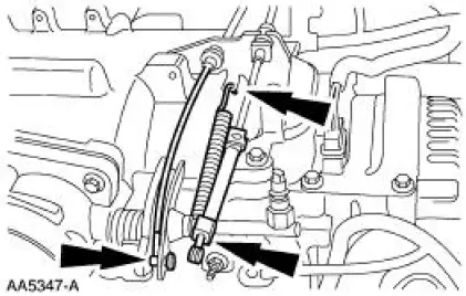
58. Connect the throttle cable and the speed control actuator cable, and install the throttle return spring.
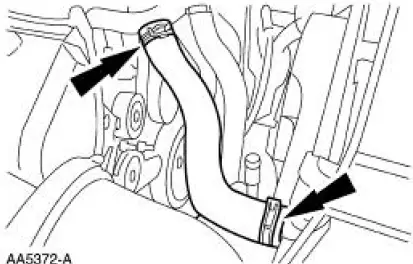
59. Install the upper radiator hose.
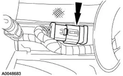
60. Connect the wiring connector.
61. Install the air cleaner assembly.
1. Install the air cleaner and the outlet tube as an assembly
2. Install the bolt.
62. Connect the mass air flow (MAF) sensor electrical connector.
63. Connect the air cleaner outlet pipe at the throttle body.
1. Connect the positive crankcase ventilation (PCV) inlet tube.
2. Tighten the clamp.
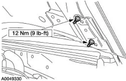
64. NOTE: Use reference marks made during removal to aid in the installation.
Install the hood and the four nuts.
65. Install the hood-to-body ground strap.
66. Connect the fuel spring lock coupling. For additional information, refer to Section.
67. Install the air intake scoop bracket. For additional information, refer to Section.
68. Connect the battery ground cable. For additional information, refer to Section..
69. Fill the crankcase with clean engine oil and check that all other fluids are at the correct levels.
70. Fill and bleed the engine cooling system. For additional information, refer to Section.
71. Fill and purge the power steering system. For additional information, refer to Section.
72. Start the engine and check for leaks. Stop the engine and recheck the fluid levels.
73. Charge the A/C system. For additional information, refer to Section.
 Engine (Assembly)
Special Tool(s)
Guides, Connecting Rod
303-442 (T93P-6136-A)
Installer, Crankshaft Vibration
Damper
303-102 (T74P-6316-B)
Installer, Front Cover Oil Seal
...
 Engine Cooling
General Specifications
Torque Specifications
...
Other materials:
Switch - Door Lock
Removal
1. CAUTION: Place a rag between the window regulator switch
plate and the door trim
panel to avoid damaging the door trim panel.
Position the window regulator switch plate (14524) aside.
1. Pull at service notch.
2. Lift to release t ...
Rear Drive Axle/Differential - Ford 8.8-Inch IRS
General Specifications
Torque Specifications
a: Use Stud and Bearing Mount EOAZ-19554-BA or equivalent meeting Ford
specification WSKM2G349-
A1.
b: With pinion flange yoke seal. ...
Ignition switch
A. Off: The ignition is off.
Note: When you switch the ignition off and leave your vehicle, do not
leave your key in the ignition. This could cause your vehicle battery to
lose charge.
B. Accessory: Allows the electrical accessories such as the radio to
ope ...
