Ford Mustang (1999-2004) Service Manual: Front Subframe - 4.6L (2V) Engine
Special Tool(s)
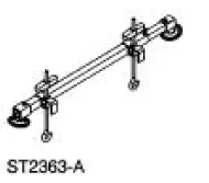 |
Support Bar, Engine 303-290-A |
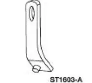 |
Lifting Bracket, Engine 303-D088 (D93P-6001-A2) |
Removal and Installation
All vehicles
1. Remove the steering gear. For additional information, refer to Section.
2. Remove the lower control arms. For additional information, refer to Section.
Vehicles with convertible top
3. Remove the front subframe support. For additional information, refer to Subframe Support - Convertible in this section
Vehicles with hard top
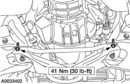
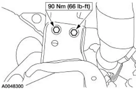
4. Remove the front subframe brace.
- Remove the bolts
All vehicles
5. Lower the vehicle.
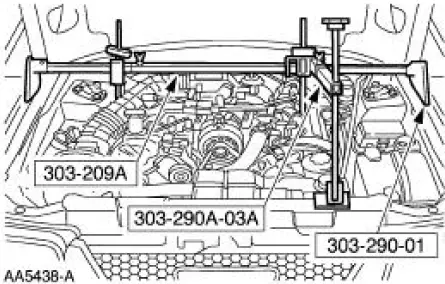
6. Install the special tool.
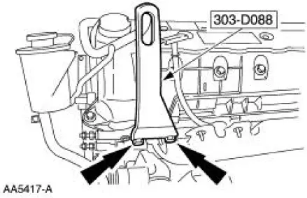
7. Install the special tool.
8. Raise and support the vehicle.
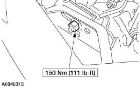
9. Remove the two engine mount nuts.
10. Lower the vehicle.
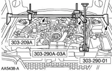
11. Using the special tool, raise and support the engine.
12. Raise the vehicle.
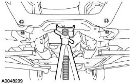
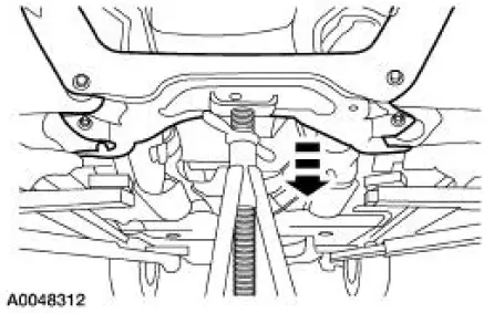
13. Support the front subframe.
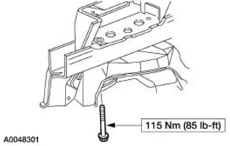
14. Remove the four front subframe lower bolts.
15. Remove the four front subframe upper bolts.
16. NOTE: Two technicians are needed to carry out this step.
Lower and remove the front subframe.
 Front Subframe - 3.8L Engine
Special Tool(s)
3-Bar Engine Support Kit
303-F072
Lifting Bracket Set, Engine
303-D095 (D94L-6001-A) (014-
00792)
Removal and Installation
All vehicles
1. Remove the st ...
 Front Subframe - 4.6L (4V) Engine
Special Tool(s)
3-Bar Engine Support Kit
303-F072
Lifting Bracket, Engine
303-D088 (D93P-6001-A2)
Removal and Installation
All vehicles
1. Remove the steering gear. For a ...
Other materials:
Temperature and Manifold Absolute Pressure (T-MAP)
Sensor - Cobra
Removal and Installation
1. Disconnect the temperature manifold absolute pressure (T-MAP)
sensor electrical connector.
2. Remove the bolts and the T-MAP sensor.
3. To install, reverse the removal procedure. ...
Navigation controls
Type 1
WARNING: Driving while distracted can result in loss of vehicle
control, crash and injury. We strongly recommend that you use
extreme caution when using any device that may take your focus off
the road. Your primary responsibility is the safe operation ...
Instrument Cluster Self-Diagnostic Mode
To enter the instrument cluster self-diagnostic mode, press and hold the
instrument cluster
SELECT/RESET button, turn the ignition switch to the RUN position, and then
continue pressing the
SELECT/RESET button (five seconds) until tESt is displayed in th ...
