Ford Mustang (1999-2004) Service Manual: Ignition Coil
Material
| Item | Specification |
| Silicone Brake Caliper Grease and Dielectric Compound D7AZ-19A331-A or equivalent | ESE-M1C171- A |
Removal and Installation
1. Disconnect the battery ground cable (14301). For additional information, refer to Section.
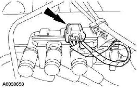
2. Disconnect the ignition coil electrical connector.
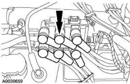
3. CAUTION: Spark plug wires (12286) must be connected to the correct ignition coil terminal. Mark spark plug wire locations before removing them.
Twist while pulling upward to disconnect the spark plug wires.
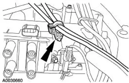
4. Disconnect the accelerator cable retaining clamp from the ignition coil stud bolt.
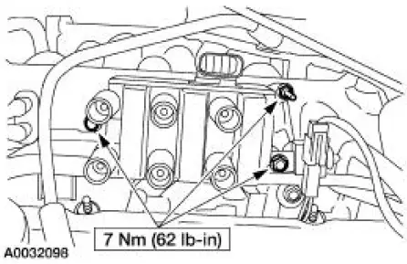
5. Remove the bolts and the ignition coil (12029).
6. NOTE: Apply silicone brake caliper grease and dielectric compound to the inside of the spark plug wire coil boot.
NOTE: Be sure to reinstall the radio ignition interference capacitor (18801) under the correct mounting bolt.
To install, reverse the removal procedure.
 Engine Ignition (Description and Operation)
The ignition coil (12029), which is mounted on the upper intake manifold, can
be described as a coil
pack containing three separate coil units. Each coil unit is individually
controlled by the power ...
 Spark Plug Wire
Special Tool(s)
Remover, Spark Plug Wire
303-106 (T74P-6666A)
Material
Item
Specification
Silicone Brake Caliper Grease
and Dielectric Compound
D7AZ-19A331-A or equiva ...
Other materials:
Reservoir
Removal
WARNING: Brake fluid contains polyglycol ethers and polyglycols.
Avoid contact with
eyes. Wash hands thoroughly after handling. If brake fluid contacts eyes,
flush eyes with
running water for 15 minutes. Get medical attention if irritation persi ...
Removal
CAUTION: Electronic modules are sensitive to static electrical
charges. If exposed to
these charges, damage may result.
1. Remove the driver air bag module. For additional information,
refer to Section.
2. Remove the passenger air bag module. For ...
Sensor - Rear
Removal
1. Remove the rear passenger seat.
2. Disconnect the rear anti-lock brake sensor electrical connector.
3. Raise and support the vehicle.
4. Remove the rear anti-lock brake sensor harness from the floor pan.
5. Remove the anti-lock brake senso ...
