Ford Mustang (1999-2004) Service Manual: Installation
WARNING: To reduce the risk of serious personal injury, read and follow all warnings, cautions and notes at the beginning of the removal procedure.
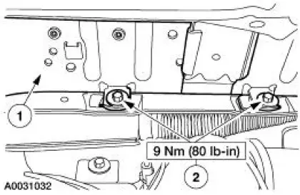
1. Install the passenger air bag module.
1. Position the passenger air bag module into the instrument panel.
2. Install the bolts.
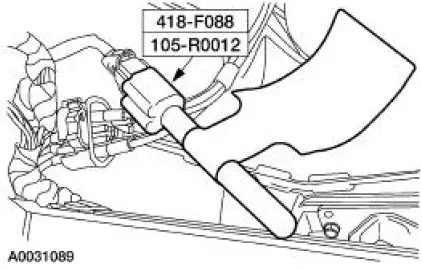
2. Remove the restraint system diagnostic tool from the vehicle harness side of the passenger air bag electrical connector.
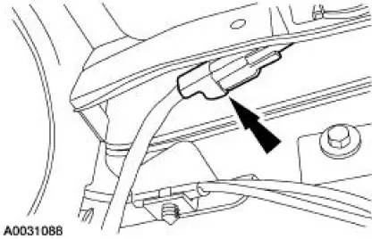
3. Connect the passenger air bag module electrical connector. Install the passenger air bag module electrical connector and pin-type retainer to the instrument panel frame.
4. Close the glove compartment.
5. Connect the battery ground cable. For additional information, refer to Section.
6. With the restraint system diagnostic tools still installed at the remaining deployable devices, prove out the supplemental restraint system (SRS). For additional information, refer to Air Bag Supplemental Restraint System (SRS) in the Diagnosis and Testing portion of this section.
7. WARNING: To avoid accidental deployment and possible personal injury, the backup power supply must be depleted before repairing or replacing any front or side air bag supplemental restraint system (SRS) components and before servicing, replacing, adjusting or striking components near the front or side air bag sensors, such as doors, instrument panel, console, door latches, strikers, seats and hood latches.
Please refer to the appropriate vehicle shop manual to determine location of the front air bag sensors.
The side air bag sensors are located at or near the base of the B-pillar.
To deplete the backup power supply energy, disconnect the battery ground cable and wait at least one minute. Be sure to disconnect auxiliary batteries and power supplies (if equipped).
Disconnect the battery ground cable and wait at least one minute. For additional information, refer to Section.
8. Restore the vehicle to operating condition.
1. WARNING: To reduce the risk of serious personal injury, read and follow all warnings, notes, and instructions in the supplemental restraint system (SRS) deactivation/reactivation procedure.
Reactivate the supplemental restraint system (SRS). For additional information, refer to Supplemental Restraint System (SRS) Deactivation and Reactivation in the General Procedures portion of this section.
2. WARNING: The restraint system diagnostic tool is for restraint system service only. Remove from the vehicle prior to road use. Failure to remove could result in injury and possible violation of vehicle safety standards.
With all the restraint system diagnostic tools removed, prove out the supplemental restraint system (SRS). For additional information, refer to Air Bag Supplemental Restraint System (SRS) in the Diagnosis and Testing portion of this section.
 Removal
WARNING: Always wear safety glasses when repairing an air bag
supplemental restraint
system (SRS) vehicle and when handling an air bag module. This will
reduce the risk of injury
in the even ...
 Clockspring
Special Tool(s)
Diagnostic Tool, Restraint
System (2 Req'd)
418-F088 (105-R0012)
...
Other materials:
Stabilizer Bar - Cobra
Removal
CAUTION: Suspension fasteners are critical parts because they affect
performance of vital
components and systems and their failure can result in major service expense. A
new part with
the same part number must be installed if installation becomes nec ...
Dual Converter Y-Pipe - 3.8L
Removal
NOTE: The RH and LH catalytic converters are serviceable separately.
1. Raise and support the vehicle. For additional information, refer to
Section.
2. CAUTION: When repairing the exhaust system or removing exhaust
components,
disconnect all heated o ...
Pinpoint Test N: DTC B1869 - Air Bag Indicator Inoperative
Normal Operation
The air bag indicator is designed to illuminate for 6 (+/-2) seconds when
the ignition switch is turned to
the RUN position. This initial 6 seconds of illumination is considered
normal operation and is called
proveout of the air bag ind ...
