Ford Mustang (1999-2004) Service Manual: Installation
CAUTION: The upper suspension arm and bushing nuts must be tightened with the suspension at curb height. Failure to do so can result in bushing failure, resulting in poor ride and handling.
NOTE: If installing a new upper suspension arm and bushing, mark the cam bolt side of the new arm in the same position as the old arm for assembly reference.
1. Install the upper suspension arm and bushing.
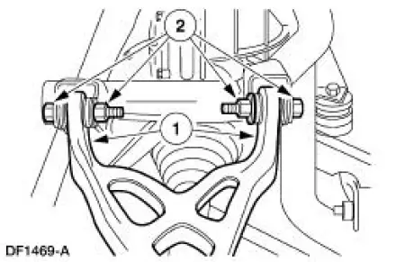
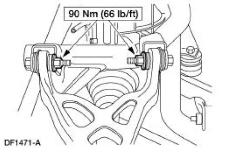
1. Position the arm and bushing on the subframe.
2. Install new bolts and nuts. Do not tighten the nuts at this time.
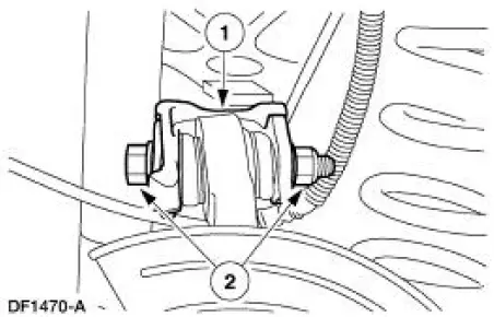
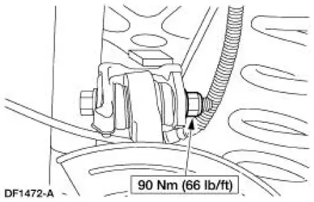
2. Connect the upper suspension arm and bushing to the knuckle.
1. Position the arm and bushing.
2. Install a new cam bolt and a new nut. Do not tighten the nut at this time.
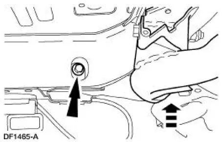
3. Raise the subframe into position and install new front bolts.
4. Install the springs. For additional information, refer to Spring-Cobra in this section.
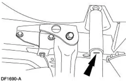
5. Position a jack stand under the lower suspension arm and bushing.
6. Raise the suspension until the shock absorber is compressed to the alignment mark (curb height).
7. Tighten the nuts.
8. Position the cam bolt so the marks are aligned. Tighten the nut.
9. Lower the suspension and remove the jack stand.
10. Install the rear brake disc.
11. Install the wheel and tire assembly.
12. Lower the vehicle.
13. Check wheel alignment, adjust if necessary.
 Removal
CAUTION: Suspension fasteners are critical parts because they affect
performance of vital
components and systems and their failure can result in major service expense. A
new part with
the same part ...
 Lower Arm
Removal
CAUTION: Suspension fasteners are critical parts because they affect
performance of vital
components and systems and their failure can result in major service expense. A
new part with
the sa ...
Other materials:
Convertible Top (Description and Operation)
Rear Window Glass Assembly
The convertible top assembly is equipped with a rear window glass
assembly. The rear window glass
assembly is permanently attached to the folding top rear window curtain
and cannot be opened. The
rear window gl ...
Stoplamps
Refer to Wiring Diagrams Cell 90 , Turn/Stop/Hazard Lamps for
schematic and connector information.
Special Tool(s)
73III Automotive Meter or
equivalent
105-R0057
Inspection and Verification
1. Verify the customer concerns.
2. Visually ...
Installation
1. Make sure the anti-rattle spring is correctly positioned in the
caliper.
2. CAUTION: Make sure guide pin boots are correctly seated or damage to
guide pins
can occur.
Install the disc brake caliper.
1. Hold the guide pins stationary.
2. Inst ...
