Ford Mustang (1999-2004) Service Manual: Installation
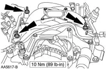
1. Install the intake manifold and gaskets, tighten the bolts in the sequence shown.
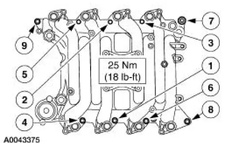
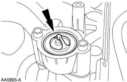
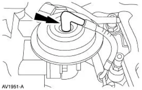
2. NOTE: The O-ring is to be installed on the top of the thermostat.
Install the water thermostat and the O-ring.
- Install a new O-ring as necessary.
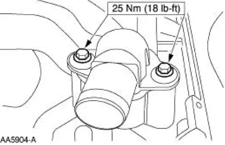
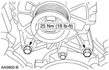
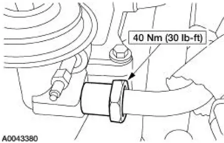
3. Install the water outlet adapter.
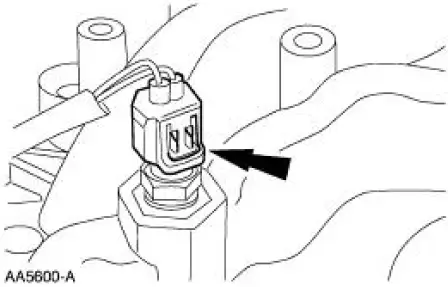
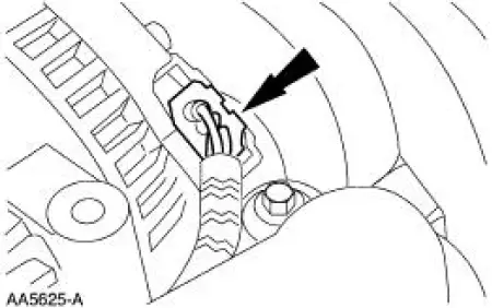
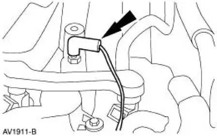
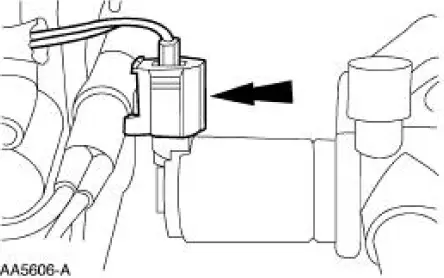
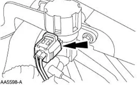
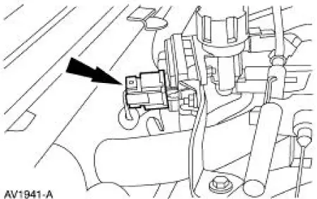
4. Connect the water temperature indicator sender.
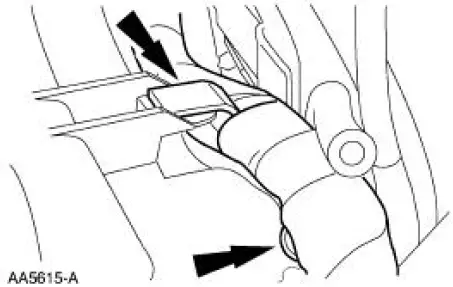
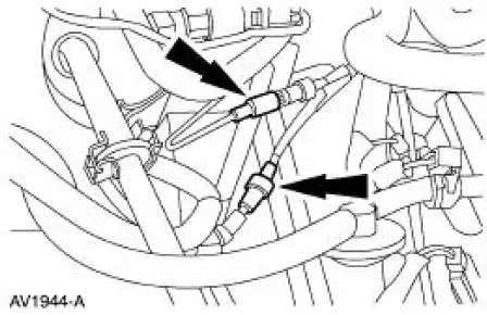
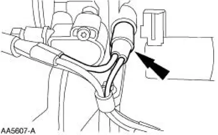
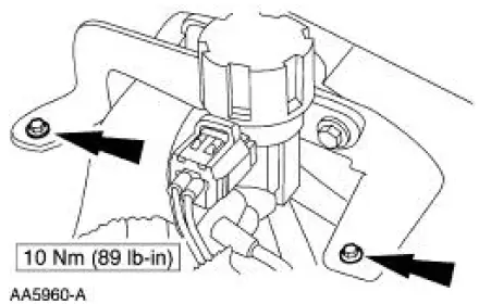
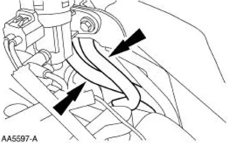
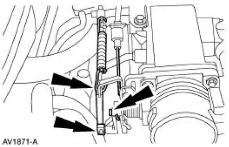
5. Position the engine harness and attach to the intake manifold in two locations.
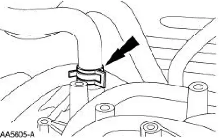
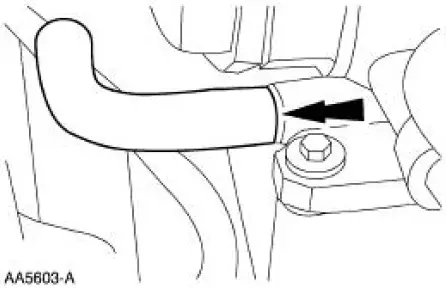
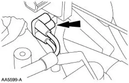
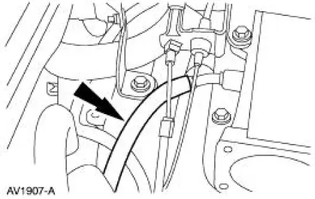
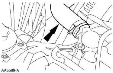
6. Connect the heater hose.
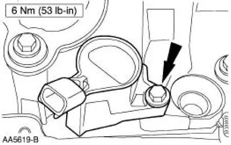
7. Install the generator.
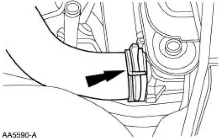
8. Connect the electrical connector.
9. Connect the battery lead.
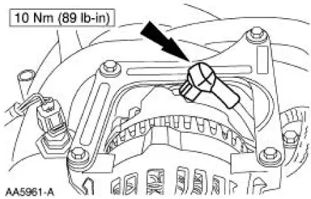
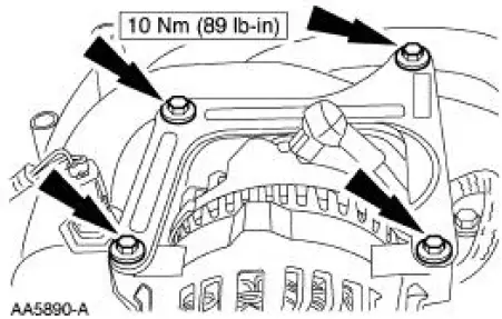
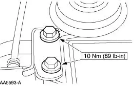
10. Install the generator support brace.
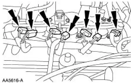
11. Install the ignition coils.
12. Install the fuel injection supply manifold and fuel injectors as an assembly.
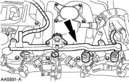
13. Install four studs.
14. Position the vacuum harness and connect to the climate control vacuum supply hoses.
15. Connect the ignition coils and the fuel injectors.
16. Connect the fuel charging ground wire.
17. Connect the fuel pressure sensor electrical connector and the vacuum hose.
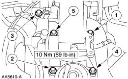
18. Install the throttle body and adapter as an assembly.
19. Tighten the bolts in the sequence shown.
20. Connect the throttle position sensor (TPS) electrical connector.
21. Connect the main vacuum supply to the base of the throttle body adapter.
22. Connect the idle air control (IAC) valve electrical connector.
23. Connect the vacuum hose to the EGR valve.
24. Connect the hose to the PCV valve.
25. Connect the PCV hose to the base of the throttle body assembly.
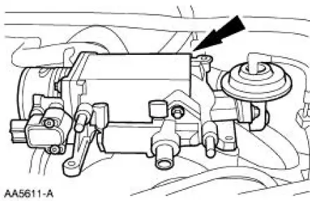
26. Connect the EGR tube to the EGR valve.
27. Install the EGR vacuum regulator solenoid bracket.
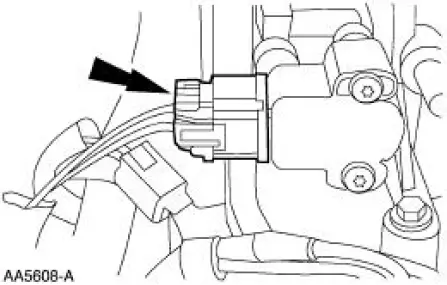
28. Connect the EGR vacuum regulator solenoid vacuum supply.
29. Connect the EGR vacuum regulator solenoid electrical connector.
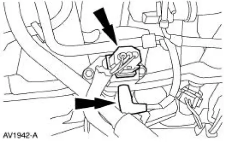
30. Connect the hoses to the differential pressure feedback EGR transducer.
31. Connect the differential pressure feedback EGR electrical connector.
32. Connect the evaporative emissions return line.
33. Install the breather tube.
34. Position the cables and install the bracket.
35. Connect the accelerator cable, speed control actuator cable and the return spring.
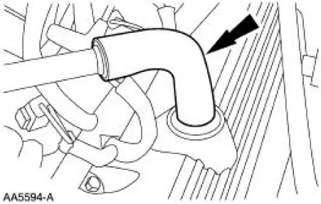
36. Connect the upper radiator hose.
37. Connect the upper radiator hose to the water outlet adapter.
38. Connect the fuel line.
39. Install the air cleaner outlet tube.
40. Refill the engine cooling system.
 Removal
1. Drain the engine cooling system.
2. Remove the air cleaner outlet tube.
3. Disconnect the fuel line.
4. Disconnect the upper radiator hose from the water outlet connector.
5. Disconnect ...
 Valve Cover RH
Material
Item
Specification
Silicone Gasket and Sealant
F7AZ-19554-EA or equivalent
WSE-M4G323-A4
Removal and Installation
1. Remove the air cleaner outlet tube. For additional inf ...
Other materials:
Installation
1. Install the upper intake manifold gasket.
2. Install the intake manifold and bolts in the sequence shown.
3. Install the PCV valve-to-intake manifold tube.
4. Connect the vacuum hoses and the electrical connector to the EGR vacuum
regulator soleno ...
Convertible Top (Description and Operation)
Rear Window Glass Assembly
The convertible top assembly is equipped with a rear window glass
assembly. The rear window glass
assembly is permanently attached to the folding top rear window curtain
and cannot be opened. The
rear window gl ...
Removal
1. Remove the differential assembly from the differential housing. For
additional information, refer
to Differential Case in this section.
2. CAUTION: Record the torque necessary to maintain rotation of the drive
pinion gear
through several revolutions prio ...
