Ford Mustang (1999-2004) Service Manual: Pinpoint Tests
PINPOINT TEST P1464: DTC P1464: A/C DEMAND OUT OF SELFTEST RANGE
| Test Step | Result / Action to Take |
| P14641 RECHECK FOR THE DTC | Yes GO to P14642 . No The system is functioning correctly. This DTC will set if the A/C is turned on when carrying out the PCM self-test. |
|
|
| P14642 CHECK PID ACCS WITH THE A/C CONTROL DISCONNECTED | Yes GO to P14643 . No INSTALL a new function selector switch. REFER to Section. REPEAT the PCM self-test and verify DTC P1464 is no longer retrieved. |
|
|
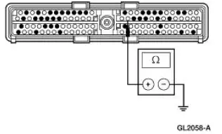
| P14643 CHECK CIRCUIT 348 (VT) FOR A SHORT TO B+ | Yes REPAIR circuit 348 (VT ) for a short to B+. REPEAT the PCM self-test and verify DTC P1464 is no longer retrieved. No INSTALL a new powertrain control module. REFER to Section. REPEAT the PCM self-test and verify DTC P1464 is no longer retrieved. |
|
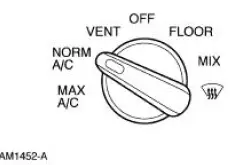
PINPOINT TEST A: INCORRECT/ERRATIC DIRECTION OF AIRFLOW FROM OUTLET
| Test Step | Result / Action to Take |
| A1 CHECK AIRFLOW FROM DEFROSTER OUTLETS | Yes GO to A2 . No If the airflow is from defroster outlets in all switch positions only under engine speed acceleration, GO to A19 . If the airflow is incorrect under one or more conditions, GO to A13 . If the airflow is correct under all conditions, RETURN to the Symptom Chart. |
|
|
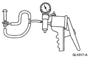
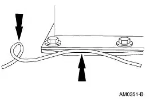
| A2 CHECK THE VACUUM SUPPLY HOSE | Yes GO to A3 . No RECONNECT the hose. TEST the system for normal operation. |
|
|
| A3 LEAK CHECK THE VACUUM SUPPLY HOSE | Yes REPAIR or INSTALL a new vacuum hose. TEST the system for normal operation. No GO to A4 . |
|
|
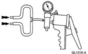
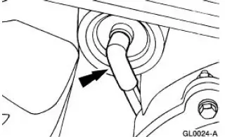
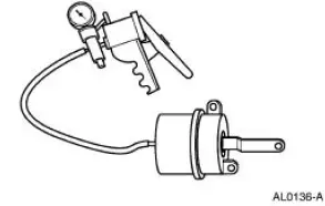
| A4 CHECK THE VACUUM CHECK VALVE | Yes GO to A6 . No GO to A5 . |
|
|
| A5 INSPECT THE VACUUM CHECK VALVE | Yes INSTALL a new A/C vacuum check valve. TEST the system for normal operation. No GO to A6 . |
|
|
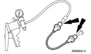
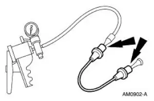
| A6 LEAK TEST THE VACUUM CHECK VALVE | Yes INSTALL a new A/C vacuum check valve. TEST the system for normal operation. No RECONNECT the A/C vacuum check valve. GO to A7 . |
|
|
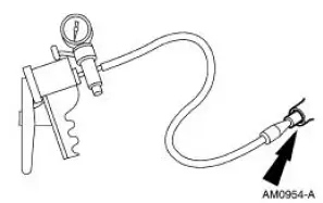
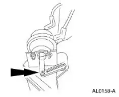
| A7 CHECK THE VACUUM RESERVOIR | Yes INSTALL a new A/C vacuum reservoir tank. TEST the system for normal operation. No RECONNECT the A/C vacuum reservoir tank. GO to A8 . |
|
|
| A8 CHECK THE SUPPLY HOSE | Yes REPAIR or INSTALL a new function selector switch supply hose. TEST the system for normal operation. No RECONNECT the function selector switch supply hose. GO to A9 . |
|
|
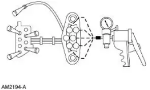
| A9 CHECK THE CONTROL ASSEMBLY | Yes NOTE the function selector switch position where the vacuum drops. GO to A10 . No RECONNECT the inline vacuum harness connector. GO to A11 . |
|
|
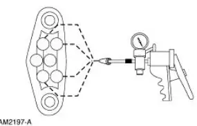
| A10 LEAK TEST THE CONTROL ASSEMBLY | Yes INSTALL a new function selector switch. TEST the system for normal operation. No RECONNECT the function selector switch vacuum connector. GO to A12 . |
|
|
| A11 CHECK THE SUPPLY HOSE FOR OBSTRUCTIONS | Yes INSTALL a new supply hose. TEST the system for normal operation. No RECONNECT the A/C damper door switch supply hose. GO to A15 . |
|
|
| A12 LEAK TEST THE JUMPER VACUUM HARNESS | Yes REPAIR or INSTALL a new vacuum jumper harness. TEST the system for normal operation. No REPAIR or INSTALL a new function selector switch. TEST the system for normal operation. |
|
|
| A13 REVIEW THE VEHICLE'S HISTORY | Yes GO to A16 . No GO to A14 . |
|
|
| A14 CHECK THE VACUUM HOSES TO DAMPER DOORS | Yes INSTALL a new vacuum hose. TEST the system for normal operation. No GO to A15 . |
|
|
| A15 CHECK THE VACUUM HARNESS | Yes GO to A16 . No INSTALL a new vacuum harness. TEST the system for normal operation. |
|
|
| A16 CHECK A/C VACUUM CIRCUIT | Yes REPAIR or INSTALL a new vacuum hose. TEST the system for normal operation. No GO to A17 . |
|
|
|
Yes RECONNECT the hose. TEST the system for normal operation. No GO to A18 . |
|
|
| A18 CHECK THE VACUUM HOSE | Yes REPAIR or INSTALL a new hose. TEST the system for normal operation. No GO to A19 . |
|
|
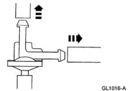
| A19 CHECK THE VACUUM CONTROL MOTOR | Yes GO to A20 . No INSTALL a new vacuum control motor. TEST the system for normal operation. |
|
|
| A20 CHECK THE VACUUM CONTROL MOTOR INSTALLATION | Yes REPAIR or INSTALL a new damper door. TEST the system for normal operation. No CONNECT the vacuum control motor arm to the door and check operation. TEST the system for normal operation. |
|
PINPOINT TEST B: INSUFFICIENT, ERRATIC, OR NO HEAT
| Test Step | Result / Action to Take |
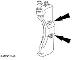
| B1 CHECK FOR CORRECT ENGINE COOLANT LEVEL | Yes GO to B2 . No GO to B3 . |
|
|
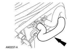
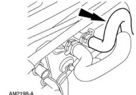
| B2 CHECK FOR HOT WATER TO THE HEATER CORE INLET HOSE | Yes GO to B4 . No TEST the engine cooling system for correct operation. |
WARNING: The heater core inlet hose will become
too hot to handle and may cause serious burns if the
system is working correctly.
|
|
| B3 CHECK THE ENGINE COOLING SYSTEM INCLUDING RADIATOR CAP FOR LEAKS | Yes GO to B4 . No Pressure test the heater core. REFER to Component Tests, Heater Core - Pressure Test. |
|
|
| B4 CHECK THE HEATER CORE OUTLET HOSE FOR HOT WATER | Yes TEST the heater core for a plugged or partially plugged condition. No GO to Pinpoint Test E . |
|
PINPOINT TEST C: THE A/C DOES NOT OPERATE/DOES NOT OPERATE CORRECTLY
| Test Step | Result / Action to Take |
| C1 CHECK THE PCM PID WACF | Yes REFER to the Powertrain Control/Emissions Diagnosis (PC/ED) manual. No GO to C2 . |
|
|
| C2 CHECK THE PCM PID WACF WITH THE A/C ON | Yes REFER to the Powertrain Control/Emissions Diagnosis (PC/ED) manual. No GO to C3 . |
|
|
| C3 CHECK THE PCM PID ACCS WITH THE A/C ON | Yes GO to C4 . No GO to C6 . |
|
|
| C4 CHECK PCM PID WAC WITH THE A/C ON | Yes GO to C20 . No GO to C5 . |
NOTE: When PCM PID WACF is YES, this is the same fault as DTC P1460.
|
|
| C5 CHECK THE INPUT SIGNAL TO THE PCM | Yes INSTALL a new powertrain control module. TEST the system for normal operation. No GO to C6 . |
|
|
| C6 CHECK THE REFRIGERANT PRESSURE | Yes GO to C7 . No REPAIR the leaks and RETEST the system for normal operation. |
|
|
| C7 CHECK THE SUPPLY TO THE FUNCTION SELECTOR SWITCH | Yes GO to C17 . No GO to C8 . |
|
|
| C8 CHECK CIRCUIT 883 (PK/LB) FOR A SHORT TO GROUND | Yes GO to C9 . No GO to C11 . |
|
|
| C9 CHECK CIRCUIT 348 (VT) FOR SHORT TO GROUND | Yes REPAIR circuit 348 (VT). TEST the system for normal operation. No GO to C10 . |
|
|
| C10 CHECK FOR A SHORTED FUNCTION SELECTOR SWITCH | Yes INSTALL a new function selector switch. REFER to Section. TEST the system for normal operation. No GO to C13 . |
|
|
| C11 CHECK CIRCUIT C198 (DG/OG) FOR A SHORT TO GROUND | Yes GO to C14 . No GO to C12 . |
|
|
| C12 CHECK THE A/C CYCLING SWITCH FOR A SHORT TO GROUND | Yes REPAIR circuit C420 (DB/YE) for a short to ground. TEST for normal operation. No INSTALL a new A/C cycling switch. REFER to Section. TEST system for normal operation. |
|
|
| C13 CHECK CIRCUIT 198 (DG/OG) FOR A SHORT TO GROUND | Yes GO to C15 . No INSTALL a new A/C fuse (15A). TEST the system for normal operation. If the fuse opens, install a new PCM. REFER to the Powertrain Control/Emissions Diagnosis (PC/ED) manual. |
|
|
| C14 CHECK THE A/C PRESSURE CUT-OFF SWITCH | Yes REPAIR circuit 198 (DG/OG) for a short to ground. TEST the system for normal operation. No INSTALL a new A/C pressure cut-off switch. |
|
|
| C15 CHECK THE FUNCTION SELECTOR SWITCH | Yes GO to C17 . No GO to C16 . |
|
|
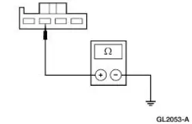
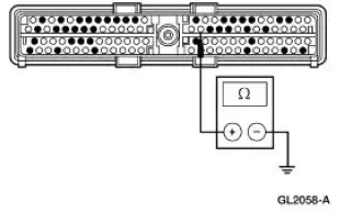
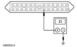
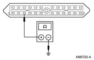
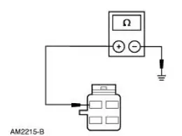
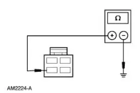
| C16 MEASURE THE RESISTANCE OF CIRCUIT 348 (VT) | Yes INSTALL a new function selector switch. REFER to Section. TEST the system for normal operation. No REPAIR circuit 348 (VT) for an open. TEST the system for normal operation. |
|
|
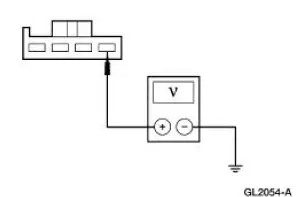
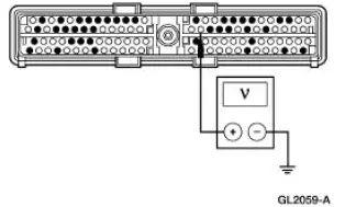
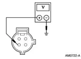
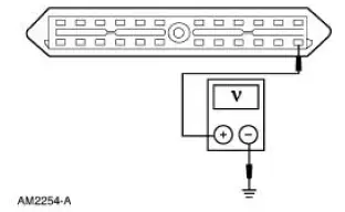
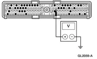
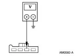
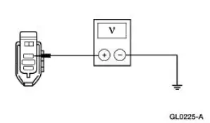
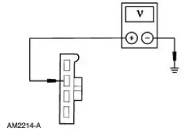
| C17 MEASURE THE VOLTAGE TO THE A/C PRESSURE CUT-OFF SWITCH | Yes GO to C19 . No GO to C18 . |
|
|
| C18 CHECK THE A/C CYCLING SWITCH | Yes INSTALL a new A/C cycling switch. REFER to Section. TEST the system for normal operation. No REPAIR circuit 420 (DB/YE) for an open. TEST the system for normal operation. |
|
|
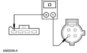
| C19 CHECK THE A/C PRESSURE CUT-OFF SWITCH | Yes INSTALL a new A/C pressure cut-off switch. REFER to Section. TEST the system for normal operation. No REPAIR circuit 198 (DG/OG) for an open. TEST the system for normal operation. |
|
|
| C20 CHECK THE GROUND CIRCUIT AT THE CONSTANT CONTROL RELAY MODULE | Yes GO to C21 . No REPAIR circuit 1205 (BK) for an open. TEST the system for normal operation. |
|
|
| C21 CHECK CIRCUIT 20 (WH/LB) AT THE CONSTANT CONTROL RELAY MODULE | Yes GO to C22 . No REPAIR circuit 20 (WH/LB) for an open. TEST the system for normal operation. |
|
|
| C22 CHECK THE POWER TO THE A/C CLUTCH | Yes GO to C24 . No GO to C23 . |
|
|
| C23 CHECK CIRCUIT 331 (PK/YE) FOR AN OPEN. | Yes GO to C24 . No REPAIR circuit 331 (PK/YE) for an open. TEST the system for normal operation. |
|
|
| C24 CHECK CIRCUIT 347 (BK/YE) | Yes GO to C25 . No REPAIR circuit 347 (BK/YE) for an open. TEST the system for normal operation. |
|
|
| C25 CHECK CIRCUIT 347 (BK/YE) FOR A SHORT TO GROUND. | Yes INSTALL a new constant control relay module. TEST the system for normal operation. No REPAIR circuit 1205 (BK) for an open. TEST the system for normal operation. |
|
PINPOINT TEST D: THE A/C IS ALWAYS ON
| Test Step | Result / Action to Take |
| D1 CHECK PCM PID WACF | Yes REPAIR circuit 331 (PK/YE) for a short to ground. TEST the system for normal operation. No GO to D2 . |
|
|
| D2 CHECK PID ACCS WITH A/C OFF | Yes GO to D3 . No GO to D5 . |
|
|
| D3 CHECK FOR A FALSE INPUT SIGNAL TO THE PCM | Yes GO to D4 . No INSTALL a new powertrain control module. REFER to Section. TEST the system for normal operation. |
|
|
| D4 CHECK CIRCUIT 198 (DG/OG) FOR A SHORT TO B+ | Yes REPAIR circuit 348 (PK) for a short to B+. TEST the system for normal operation. No INSTALL a new function selector switch. REFER to Section. TEST the system for normal operation. |
|
|
| D5 CHECK FOR A SHORTED CLUTCH INPUT | Yes INSTALL a new constant control relay module. TEST the system for normal operation. No CHECK the clutch air gap. REFER to Air Conditioning (A/C) Clutch Air Gap Adjustment . |
|
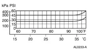
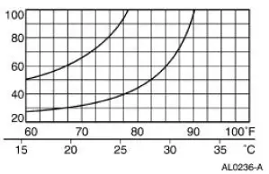
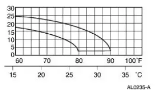
PINPOINT TEST E: INSUFFICIENT A/C COOLING
| Test Step | Result / Action to Take |
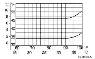
| E1 CHECK THE CENTER A/C REGISTER DISCHARGE TEMPERATURE | Yes The tests indicate that the system is functioning normally. No GO to E2 . |
|
|
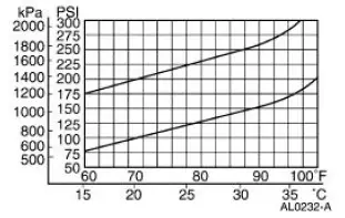
| E2 CHECK FOR NORMAL DISCHARGE PRESSURE | Yes GO to E3 . No GO to E8 . |
|
|
| E3 EVALUATE THE SYSTEM LOW PRESSURE PERFORMANCE | Yes GO to E4 . No GO to E6 . |
|
|
| E4 CHECK FOR A SLOW OR CONTINUOUS RUN A/C CLUTCH CYCLE RATE | Yes GO to E5 . No INSTALL a new A/C evaporator core due to a partially restricted or plugged condition. REFER to Section. TEST the system for normal operation. |
|
|
| E5 CHECK FOR A LONG OR CONTINUOUS A/C CLUTCH OFF TIME | Yes DISCHARGE and RECOVER the system to remove excessive moisture or refrigerant oil. REFER to Air Conditioning (A/C) System Recovery, Evacuation and Charging . TEST the system for normal operation. No GO to E7 . |
|
|
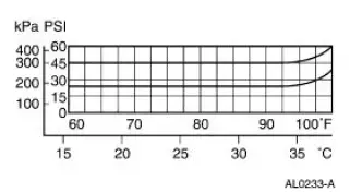
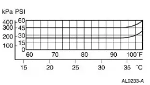
| E6 CHECK FOR A HIGH SUCTION PRESSURE | Yes REMOVE the A/C evaporator core orifice to repair missing or damaged (leaking) O-ring seals. REFER to Section. TEST the system for normal operation. No INSTALL a new A/C cycling switch when the intersection of the two lines is below the lower limit. REFER to Section. TEST the system for normal operation. |
|
|
| E7 CHECK THE AMBIENT TEMPERATURE | Yes This is normal operation for the refrigerant system in high humidity conditions. No DISCHARGE and RECOVER the system to correct an overcharge condition. REFER to Air Conditioning (A/C) System Recovery, Evacuation and Charging . TEST the system for normal operation. |
|
|
| E8 CHECK FOR A HIGH DISCHARGE PRESSURE | Yes GO to E9 . No GO to E11 . |
|
|
| E9 CHECK FOR A NORMAL LOW PRESSURE | Yes REFER to Section to diagnose the engine cooling system. TEST the system for normal operation. No GO to E10 . |
|
|
| E10 CHECK FOR A NORMAL TO LOW SUCTION PRESSURE | Yes INSTALL a new A/C evaporator core orifice due to a partially restricted or plugged condition. REFER to Section. TEST the system for normal operation. No INSPECT the A/C condenser core (19712) for a partially blocked or inadequate airflow. TEST the system for normal operation. |
|
|
| E11 CHECK FOR A NORMAL SUCTION PRESSURE | Yes GO to E12 . No GO to E15 . |
|
|
| E12 CHECK FOR A SLOW A/C CLUTCH CYCLE RATE | Yes INSTALL a new evaporator to compressor suction line (19D742) due to a partially restricted or plugged condition. REFER to Section. TEST the system for normal operation. No GO to E13 . |
|
|
| E13 CHECK FOR A NORMAL A/C CLUTCH OFF TIME | Yes INSPECT the A/C evaporator core due to a low or restricted airflow. TEST the system for normal operation. No GO to E14 . |
|
|
| E14 CHECK FOR A LONG A/C CLUTCH OFF TIME | Yes INSTALL a new A/C condenser core due to a partially restricted or plugged condition. REFER to Section. TEST the system for normal operation. No EVACUATE and RECHARGE the system when the intersection of the two lines is below the lower limit. REFER to Air Conditioning (A/C) System Recovery, Evacuation and Charging . TEST the system for normal operation. |
|
|
| E15 CHECK FOR A MISSING A/C EVAPORATOR CORE ORIFICE | Yes INSTALL a new A/C evaporator core orifice. REFER to Section. TEST the system for normal operation. No INSTALL a new A/C compressor due to low performance. REFER to Section. TEST the system for normal operation. |
|
PINPOINT TEST F: NO OPERATION IN ALL TEMPERATURE SETTINGS
| Test Step | Result / Action to Take |
| F1 CHECK THE TEMPERATURE CONTROL | Yes The temperature blend door is functioning correctly. RETURN to the symptom chart. No GO to F2 . |
|
|
| F2 CHECK FOR A BROKEN A/C TEMPERATURE CONTROL CABLE | Yes INSTALL a new evaporator housing. REFER to Section. No INSTALL a new temperature control cable assembly. |
|
PINPOINT TEST G: THE BLOWER MOTOR DOES NOT OPERATE/DOES NOT OPERATE CORRECTLY
| Test Step | Result / Action to Take |
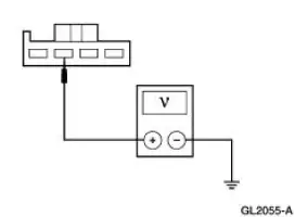
| G1 CHECK FOR VOLTAGE AT C238 | Yes GO to G2 . No GO to G4 . |
|
|
| G2 CHECK THE BLOWER MOTOR FOR VOLTAGE | Yes INSTALL a new blower motor. REFER to Section. TEST the system for normal operation. No GO to G3 . |
|
|
| G3 CHECK THE A/C BLOWER MOTOR JUMPER WIRE | Yes REPAIR circuit 261 (OG/BK). TEST the system for normal operation. No INSTALL a new blower motor. REFER to Section. TEST the system for normal operation. |
|
|
| G4 CHECK CIRCUIT 249 (DB/LG) | Yes GO to G5 . No GO to G8 . |
|
|
| G5 CHECK CIRCUIT 249 (DB/LG) FOR OPEN | Yes REPAIR circuit 249 (DB/LG) for an open. TEST the system for normal operation. No GO to G6 . |
|
|
| G6 CHECK THE BLOWER MOTOR GROUND | Yes GO to G7 . No GO to G10 . |
|
|
| G7 CHECK CIRCUIT 261 (OG/BK) FOR AN OPEN CIRCUIT | Yes REPAIR the blower motor jumper. TEST the system for normal operation. No INSTALL a new blower motor. REFER to Section. TEST the system for normal operation. |
|
|
| G8 CHECK CIRCUIT 249 (DB/LG) FOR AN OPEN CIRCUIT | Yes REPAIR circuit 249 (DB/LG) for an open. TEST the system for normal operation. No GO to G9 . |
|
|
| G9 CHECK CIRCUIT 181 (BN/OG), FOR VOLTAGE | Yes INSTALL a new function selector switch. REFER to Section. TEST the system for normal operation. No REPAIR circuit 181 (BN/OG) for an open. TEST the system for normal operation. |
|
|
| G10 CHECK CIRCUIT 1205 (BK) FOR AN OPEN | Yes INSTALL a new blower motor switch. REFER to Section. TEST the system for normal operation. No REPAIR circuit 1205 (BK). TEST the system for normal operation. |
|
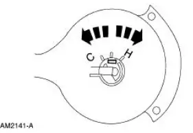
PINPOINT TEST H: THE BLOWER MOTOR OPERATES CONTINUOUSLY IN HIGH SPEED
| Test Step | Result / Action to Take |
| H1 CHECK THE FUNCTION SELECTOR SWITCH | Yes GO to H2 . No If the blower motor operates in the OFF position, GO to H4 |
|
|
| H2 CHECK CIRCUIT 261 (OG/BK) FOR A SHORT TO GROUND | Yes GO to H3 . No REPAIR circuit 261 (OG/BK) for a short to ground. TEST the system for normal operation. |
|
|
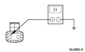
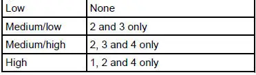
| H3 CHECK THE BLOWER MOTOR SWITCH OPERATION | Yes INSTALL a new heater blower motor switch resistor. REFER to Section. TEST the system for normal operation. No INSTALL a new heater blower motor switch. REFER to Section. TEST the system for normal operation |
Blower Motor Switch Test
|
|
| H4 CHECK THE FUNCTION SELECT SWITCH FOR A SHORT TO BATTERY | Yes INSTALL a new function selector switch. REFER to Section. TEST the system for normal operation. No REPAIR circuit 249 (DB/LG) for a short to battery. TEST the system for normal operation. |
|

PINPOINT TEST I: NO OPERATION IN HIGH BLOWER SETTING
| Test Step | Result / Action to Take |
| I1 CHECK CIRCUIT 261 (OG/BK) FOR AN OPEN CIRCUIT | Yes GO to I2 . No REPAIR circuit 261 (OG/BK) for an open circuit. TEST the system for normal operation. |
|
|
| I2 CHECK CIRCUIT 1205 (BK) FOR AN OPEN | Yes REPAIR circuit 1205 (BK) for an open. TEST the system for normal operation. No INSTALL a new blower motor switch. REFER to Section. TEST the system for normal operation. |
|
PINPOINT TEST J: NO OPERATION IN LOWER SPEEDS
| Test Step | Result / Action to Take |
| J1 CHECK CIRCUIT 261 (OG/BK) FOR AN OPEN | Yes GO to J2 . No REPAIR circuit 261 (OG/BK) for an open circuit between the blower motor and the blower motor resistor. TEST the system for normal operation. |
|
|
| J2 CHECK CIRCUIT 1205 (BK) FOR AN OPEN | Yes INSTALL a new blower motor resistor. REFER to Section. TEST the system for normal operation. No REPAIR circuit 1205 (BK) for an open between the blower motor resistor and ground. TEST the system for normal operation. |
|
 Symptom Chart
Condition
Possible Sources
Action
Incorrect/erratic direction
of airflow from outlet(s)
No vacuum to A/C heater
function switch selector.
A/C heater funct ...
 Component Tests
Heater Core
WARNING: Carbon monoxide gas is colorless, odorless and dangerous.
If it is necessary
to operate the engine with the vehicle in a closed area such as a garage,
always use an exhaust
...
Other materials:
Brake Caliper - Cobra
Removal
1. Raise and support the vehicle.
2. Remove the tire and wheel assembly.
3. Remove the caliper locating pin E-clip.
4. Remove the caliper locating pin.
5. Remove the front brake flow bolt.
6. Remove the caliper.
7. Remove the brake pa ...
Crankshaft Runout
Special Tool(s)
Dial Indicator Gauge with
Holding Fixture
100-002 (TOOL-4201-C) or
equivalent
1. NOTE: Crankshaft main bearing journals must be within
specifications before checking runout.
Use the Dial Indicator Gauge with Holding Fixtur ...
Installation
1. CAUTION: Do not allow grease, oil, brake fluid or other
contaminants to contact the
pad lining material. Do not install contaminated pads.
NOTE: Install all hardware supplied with pad kits.
Install the pads.
1. Install the new pad slippers. ...
