Ford Mustang (1999-2004) Service Manual: Pinpoint Tests
PINPOINT TEST A: THE CONTROL ILLUMINATION IS INOPERATIVE
| Test Step | Result / Action to Take |
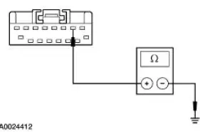
| A1 CHECK PARKING LAMPS | Yes Place the headlamp switch in the OFF position. GO to A2 . No REFER to Section. |
|
|
| A2 CHECK HEADLAMP SWITCH | Yes RECONNECT the headlamp switch. GO to A3 . No INSTALL a new headlamp switch. REFER to Section. TEST the system for normal operation. |
|
|
| A3 CHECK CIRCUIT 1045 (DB/WH) | Yes REPAIR circuit 19 (LB/RD). TEST the system for normal operation. No REPAIR circuit 1045 (DB/WH). TEST the system for normal operation. |
|
PINPOINT TEST B: THE INSTRUMENT CLUSTER ILLUMINATION IS INOPERATIVE
| Test Step | Result / Action to Take |
| B1 CHECK VOLTAGE TO INSTRUMENT CLUSTER ILLUMINATION | Yes GO to B2 . No REPAIR the circuit. TEST the system for normal operation. |
|
|
| B2 CHECK GROUND TO INSTRUMENT CLUSTER | Yes INSTALL a new instrument cluster. REFER to Section. TEST the system for normal operation. No REPAIR the circuit. TEST the system for normal operation. |
|
PINPOINT TEST C: THE CLIMATE CONTROL ILLUMINATION IS INOPERATIVE
| Test Step | Result / Action to Take |
| C1 CHECK VOLTAGE TO CLIMATE CONTROL ILLUMINATION | Yes GO to C2 . No REPAIR the circuit. TEST the system for normal operation. |
|
|
| C2 CHECK GROUND TO CLIMATE CONTROL | Yes INSTALL new illumination bulb(s). REFER to Section . No REPAIR the circuit. TEST the system for normal operation. |
|
PINPOINT TEST D: THE AUDIO SYSTEM ILLUMINATION IS INOPERATIVE
| Test Step | Result / Action to Take |
| D1 CHECK VOLTAGE TO AUDIO UNIT | Yes GO to D2 . No REPAIR the circuit. TEST the system for normal operation. |
|
|
| D2 CHECK GROUND TO AUDIO UNIT | Yes REMOVE the audio unit and SEND it to an authorized Ford audio systems repair facility. TEST the system for normal operation. No REPAIR the circuit. TEST the system for normal operation. |
|

PINPOINT TEST E: A SINGLE ILLUMINATION SOURCE IS INOPERATIVE
| Test Step | Result / Action to Take |
| E1 CHECK VOLTAGE TO THE SINGLE ILLUMINATION SOURCE | Yes GO to E2 . No REPAIR the circuit. TEST the system for normal operation. |
|
|
| E2 CHECK SINGLE ILLUMINATION SOURCE GROUND | Yes INSTALL a new component in question. TEST the system for normal operation. No REPAIR the circuit. TEST the system for normal operation. |
|
Instrument Cluster Bulb
Removal and Installation
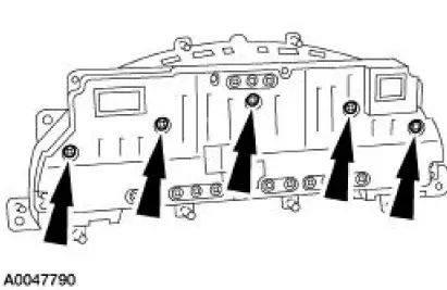
1. Remove the instrument cluster. For additional information, refer to Section.
2. Remove the necessary instrument cluster bulbs by rotating the bulb one quarter turn counterclockwise and lifting straight out of the instrument cluster.
3. To install, reverse the removal procedure.
 Inspection and Verification
NOTE: A new instrument cluster must be reconfigured.
NOTE: The instrument panel dimmer switch is a part of the headlamp
switch.
1. Verify the customer concern.
2. Visually inspect for obvious signs ...
 Instrument Cluster (Description and Operation)
The instrument cluster (10849) consists of the following components:
Instrument Cluster-Base 3.8L Engine
Instrument Cluster-Base 4.6L Engine
Instrument Cluster-Cobra
...
Other materials:
Instrument Cluster (Diagnosis and Testing)
Refer to Wiring Diagrams Cell 60 , Instrument Cluster for schematic and
connector information.
Special Tool(s)
Worldwide Diagnostic System
(WDS)
418-F224,
New Generation STAR (NGS)
Tester
418-F052, or equivalent
diagnostic tool
...
Rear Suspension
Torque Specifications
WARNING: All vehicles are equipped with gas pressurized shock absorbers
which will
extend unassisted. Do not apply heat or flame to the shock absorbers during
removal or
component servicing. Failure to follow these instructions can re ...
Inspection and Verification
WARNING: When servicing starter motor or carrying out other underhood
work in the
vicinity of the starter motor, be aware that the heavy gauge battery input lead
at the starter
solenoid is "electrically hot" at all times. A protective cap or boot is
provide ...
