Ford Mustang Service Manual: Instrument Cluster and Panel Illumination (Diagnosis and Testing)
Instrument Cluster and Panel Illumination (Diagnosis and Testing)
Refer to Wiring Diagrams Cell 71 , Instrument Illumination for schematic and connector information.
Special Tool(s)
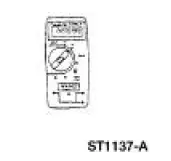
![]() |
73III Automotive Meter 105-R0057 or equivalent |
Inspection and Verification
NOTE: A new instrument cluster must be reconfigured.
NOTE: The instrument panel dimmer switch is a part of the headlamp switch.
1. Verify the customer concern.
2. Visually inspect for obvious signs of electrical damage.
Visual Inspection Chart
Electrical |
|
3. If the fault is not visually evident, determine the symptom and proceed to the Symptom Chart.
Symptom Chart
Condition | Possible Sources | Action |
|
|
|
|
|
|
|
|
|
|
|
|
|
|
|
Pinpoint Tests
PINPOINT TEST A: THE CONTROL ILLUMINATION IS INOPERATIVE
Test Step | Result / Action to Take |
A1 CHECK PARKING LAMPS | Yes Place the headlamp switch in the OFF position. GO to A2 . No REFER to Section. |
|
|
A2 CHECK HEADLAMP SWITCH | Yes RECONNECT the headlamp switch. GO to A3 . No INSTALL a new headlamp switch. REFER to Section. TEST the system for normal operation. |
|
|
A3 CHECK CIRCUIT 1045 (DB/WH) | Yes REPAIR circuit 19 (LB/RD). TEST the system for normal operation. No REPAIR circuit 1045 (DB/WH). TEST the system for normal operation. |
|
PINPOINT TEST B: THE INSTRUMENT CLUSTER ILLUMINATION IS INOPERATIVE
Test Step | Result / Action to Take |
B1 CHECK VOLTAGE TO INSTRUMENT CLUSTER ILLUMINATION | Yes GO to B2 . No REPAIR the circuit. TEST the system for normal operation. |
|
|
B2 CHECK GROUND TO INSTRUMENT CLUSTER | Yes INSTALL a new instrument cluster. REFER to Section. TEST the system for normal operation. No REPAIR the circuit. TEST the system for normal operation. |
|
PINPOINT TEST C: THE CLIMATE CONTROL ILLUMINATION IS INOPERATIVE
Test Step | Result / Action to Take |
C1 CHECK VOLTAGE TO CLIMATE CONTROL ILLUMINATION | Yes GO to C2 . No REPAIR the circuit. TEST the system for normal operation. |
|
|
C2 CHECK GROUND TO CLIMATE CONTROL | Yes INSTALL new illumination bulb(s). REFER to Section . No REPAIR the circuit. TEST the system for normal operation. |
|
PINPOINT TEST D: THE AUDIO SYSTEM ILLUMINATION IS INOPERATIVE
Test Step | Result / Action to Take |
D1 CHECK VOLTAGE TO AUDIO UNIT | Yes GO to D2 . No REPAIR the circuit. TEST the system for normal operation. |
|
|
D2 CHECK GROUND TO AUDIO UNIT | Yes REMOVE the audio unit and SEND it to an authorized Ford audio systems repair facility. TEST the system for normal operation. No REPAIR the circuit. TEST the system for normal operation. |
|
PINPOINT TEST E: A SINGLE ILLUMINATION SOURCE IS INOPERATIVE
Test Step | Result / Action to Take |
E1 CHECK VOLTAGE TO THE SINGLE ILLUMINATION SOURCE | Yes GO to E2 . No REPAIR the circuit. TEST the system for normal operation. |
|
|
E2 CHECK SINGLE ILLUMINATION SOURCE GROUND | Yes INSTALL a new component in question. TEST the system for normal operation. No REPAIR the circuit. TEST the system for normal operation. |
|
Instrument Cluster Bulb
Removal and Installation
1. Remove the instrument cluster. For additional information, refer to Section.
2. Remove the necessary instrument cluster bulbs by rotating the bulb one quarter turn counterclockwise and lifting straight out of the instrument cluster.
3. To install, reverse the removal procedure.
Instrument Cluster and Panel Illumination
The instrument cluster and panel illumination system illuminates the
following components:
instrument cluster (10849)
audio unit (18806)
A/C-heater control
fog lamp switch
transmission range in ...
Inspection and Verification
NOTE: A new instrument cluster must be reconfigured.
NOTE: The instrument panel dimmer switch is a part of the headlamp
switch.
1. Verify the customer concern.
2. Visual ...
Other materials:
Assembly
Disassembly
1. Remove the differential assembly from the differential housing. For
additional information, refer
to Differential Case in this section.
2. Remove the 10 bolts.
3. CAUTION: Do not damage the threads in the bolt holes.
Insert a punch in the b ...
Removal
Removal
1. Remove the nuts and position the radio ignition interference capacitors
aside.
2. Remove the valve covers. For additional information, refer to Valve Cover
RH and Valve Cover
LH in this section.
3. Remove the cooling fan.
4. Remove the accesso ...
Principles of Operation
There are four main principles involved with the basic theory of
operation:
heat transfer
latent heat of vaporization
relative humidity
effects of pressure
Heat Transfer
If two substances of different temperature are pl ...