Ford Mustang (1999-2004) Service Manual: Pinpoint Tests - OSC Equipped Vehicles
Special Tool(s)
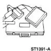 |
Breakout Box, EEC-V Control System 418-049 (T94L-50-EEC-V) or equivalent |
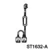 |
MLP-TR Cable 418-F107 (007-00111) or equivalent |
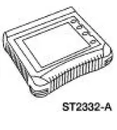 |
Worldwide Diagnostic System (WDS) 418-F224 New Generation STAR (NGS) Tester 418-F052 or equivalent scan tool |
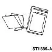 |
Transmission Tester 307-F016 (007-00130) or equivalent |
 |
Trans Tester TR/MLP Overlay and Manual 007-00131 or equivalent |
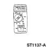 |
73 III Automotive Meter 105-R0057 or equivalent |
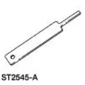 |
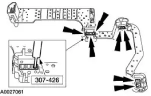
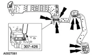
Gauge, Transmission Solenoid Connectors 307-426 |
Any time an electrical connector or solenoid body is disconnected, inspect the connector for pin condition, corrosion and contamination. Also inspect the connector seal for damage. Clean, repair or install a new connector as required.
Shift Solenoids Pre-Diagnosis
Use the following shift solenoid operation information when carrying out Pinpoint Test A.
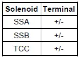
Solenoid Operation Chart
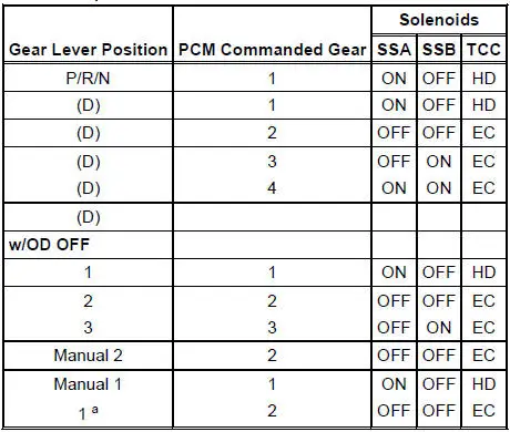
a - When a manual pull-in occurs above a calibrated speed the transmission will downshift from the higher gear until the vehicle speed drops below this calibrated speed.
EC = Electronically controlled.
HD = Hydraulically disabled.
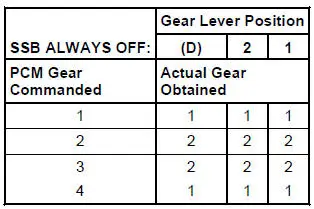
Shift Solenoid Failure Mode Chart "Always Off"
Failed off due to powertrain control module and or vehicle wiring concerns, shift solenoid electrically or hydraulically stuck off.
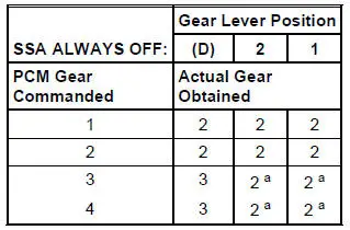
a - No engine braking.
Shift Solenoid Failure Mode Chart "Always On"
Failed on due to powertrain control module and or vehicle wiring concerns, shift solenoid electrically or hydraulically stuck on.
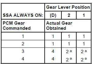
a - No engine braking.
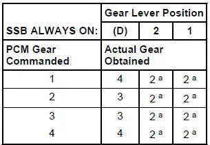
a - No engine braking.
PINPOINT TEST A: SHIFT AND TORQUE CONVERTER CLUTCH SOLENOIDS
| Test Step | Result / Action to Take |
| NOTE: Read and record all DTCs. All digital TR Sensor and VSS DTCs must be repaired before entering Output State Control (OSC). | |
| NOTE: Refer to the Transmission Internal Harness illustration preceding these pinpoint tests. | |
| NOTE: Refer to the Transmission Vehicle Harness Connector illustration preceding these pinpoint tests. | |
| A1 ELECTRONIC DIAGNOSTICS | Yes GO to A2 . No REPEAT procedure to enter Trans-Bench Mode. If vehicle did not enter Trans-Bench Mode, REFER to the Powertrain Control/Emissions Diagnosis (PC/ED) manual for diagnosis of PCM. |
|
|
| A2 WIGGLE TEST | Yes REPAIR open or short in the vehicle harness or connector. No GO to A3 . |
|
|
| A3 SOLENOID FUNCTIONAL CHECK | Yes GO to A4 . No GO to A5 . |
|
|
| A4 OSC TRANS-DRIVE MODE (GR_CM OR TCC) | Yes CLEAR all DTCs. ROAD TEST to verify if concern is still present. If concern is still present, REFER to Diagnosis By Symptom in this section to diagnose shift or torque converter concern. No GO to A5 . |
|
|
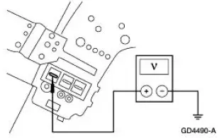
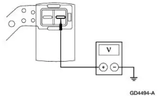
| A5 CHECK FOR BATTERY VOLTAGE | Yes GO to A6 . No CHECK for open or short circuit in harness, or solenoid. |
|
|
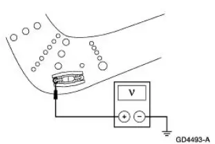
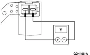
| A6 ELECTRICAL SIGNAL CHECK | Yes GO to A7 . No CHECK for open or short circuit in harness, solenoid or a PCM concern. |
|
|
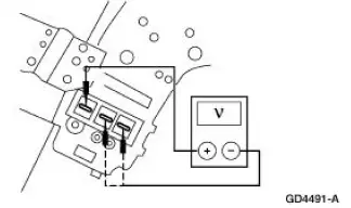
| A7 CHECK LEAD FRAME CONNECTIONS | Yes INSTALL a new lead frame. GO to A8 . No GO to A8 . |
|
|
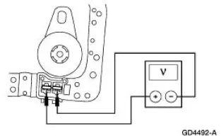
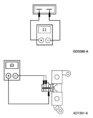
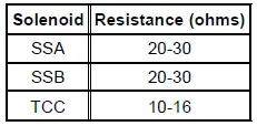
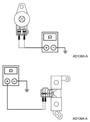
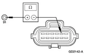
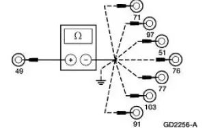
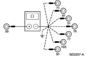
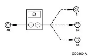
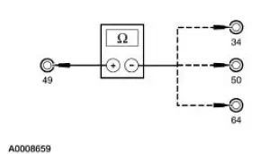
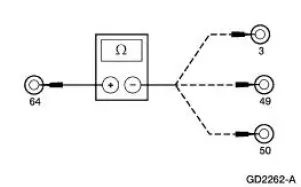
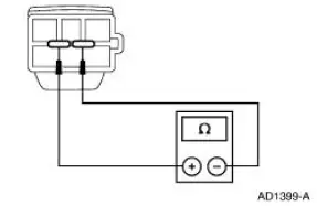
| A8 CHECK SOLENOID RESISTANCE AT SOLENOID | Yes GO to A9 . No INSTALL a new solenoid. |
|
|
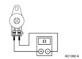
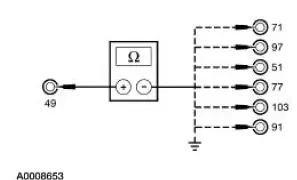
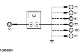
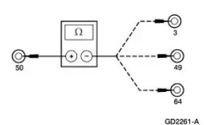
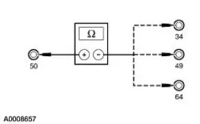
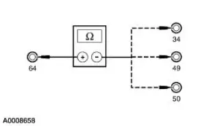
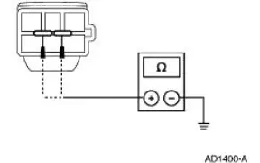
| A9 CHECK SOLENOID FOR SHORT TO GROUND | Yes INSTALL a new solenoid. No REFER to Diagnosis By Symptom in this section for diagnosis of shift or torque converter concerns. |
|
|
PINPOINT TEST B: TRANSMISSION FLUID TEMPERATURE (TFT) SENSOR
| Test Step | Result / Action to Take |
| NOTE: Refer to the Transmission Connector Layouts preceding these pinpoint tests. | |
| B1 ELECTRONIC DIAGNOSTICS | Yes GO to B2 . No REPEAT procedure to enter PID. If vehicle did not enter PID, REFER to the Powertrain Control/Emissions Diagnosis (PC/ED) manual for diagnosis of PCM. |
|
|
| B2 WARM-UP/COOL-DOWN CYCLE | Yes If the TFT PIDs increase as the transmission is warmed or decrease as the transmission is cooled, CLEAR all DTCs. ROAD TEST to verify if concern is still present. If concern is still present, REFER to Diagnosis By Symptom in this section to diagnose transmission overheating. If the TFT or TFTV drop in and out of range, INSPECT for intermittent concern in the internal/external harness, sensor or connector. No GO to B3 |
|
|
| B3 ELECTRICAL SIGNAL CHECK | Yes GO to B4 . No CHECK for open or short circuit in vehicle harness, internal harness or a PCM concern. |
|
|
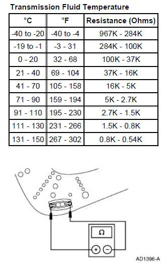
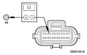
| B4 CHECK RESISTANCE OF TFT SENSOR | Yes REFER to Diagnosis By Symptom in this section to diagnose an overheating concern. No INSTALL a new internal harness (sensor is part of harness). |
|
|
PINPOINT TEST C: DIGITAL TRANSMISSION RANGE (TR) SENSOR
| Test Step | Result / Action to Take |
| NOTE: Refer to the Digital Transmission Range (TR) Sensor Connector illustration preceding these pinpoint tests. | |
| NOTE: Refer to the Digital Transmission Range (TR) Sensor Diagnosis Chart preceding these pinpoint tests. | |
| C1 VERIFY DIAGNOSTIC TROUBLE CODES | Yes GO to C4 . No GO to C2 . |
|
|
| C2 VERIFY DIGITAL TRANSMISSION RANGE SENSOR ALIGNMENT | Yes GO to C3 . No ADJUST the digital TR sensor. PLACE transmission range selector lever in P and CLEAR DTCs. REPEAT OBD Tests.GO to C3 . |
|
|
| C3 VERIFY SHIFT CABLE/LINKAGE ADJUSTMENT | Yes GO to C4 . No ADJUST the shift cable/linkage. |
|
|
| C4 CHECK ELECTRICAL SIGNAL OPERATION | Yes REPAIR as required. CLEAR DTCs and REPEAT OBD Tests. No If diagnosing a DTC, GO to C5 . If diagnosing a starting concern or a reversing lamp concern, GO to C10 . |
|
|
| C5 CHECK ELECTRICAL SYSTEM OPERATION (DIGITAL TR AND PCM) | Yes The problem is not in the digital TR sensor system. REFER to Diagnosis By Symptom in this section for further diagnosis. No If TR_D changes when wiggling harness, tapping on the sensor, or driving the vehicle, the problem may be intermittent. GO to C6 . |
|
|
| C6 CHECK DIGITAL TRANSMISSION RANGE SENSOR OPERATION | Yes Concern is not in the digital TR sensor, GO to C7 . No INSTALL a new digital TR sensor. CLEAR DTCs and REPEAT OBD Tests. |
|
|
| C7 CHECK PCM HARNESS CIRCUITS FOR OPENS | Yes GO to C8 . No REPAIR open circuit(s). RECONNECT all components. CLEAR DTCs. REPEAT OBD Tests. |
|
|
| C8 CHECK PCM HARNESS CIRCUITS FOR SHORT TO GROUND OR POWER | Yes GO to C9 . No REPAIR short circuit(s). RECONNECT all components. CLEAR DTCs. REPEAT OBD Tests. |
|
|
| C9 CHECK FOR SHORT BETWEEN TR/PCM INPUT SIGNAL CIRCUITS | Yes INSTALL a new PCM. RECONNECT all components. CLEAR DTCs. REPEAT OBD Tests. No REPAIR shorts on circuits having less than 10,000 ohms between other TR/PCM input signal circuits. RECONNECT all components. CLEAR DTCs. REPEAT OBD Tests. |
|
|
| C10 CHECK THE NON-PCM INTERNAL CIRCUITS OF SENSOR | Yes Concern is not in the digital TR sensor. For starting system concerns, REFER to Section. For reversing lamp concerns, REFER to Section. For optional circuits, REFER to the Powertrain Control/Emissions Diagnosis (PC/ED) manual for diagnosis. No INSTALL a new digital TR sensor. CLEAR DTCs. REPEAT OBD Tests. |
|
|

PINPOINT TEST D: ELECTRICAL PRESSURE CONTROL (EPC) SOLENOID
| Test Step | Result / Action to Take |
| NOTE: Refer to the Transmission Internal Harness illustration preceding these pinpoint tests. | |
| NOTE: Read and record all DTCs. All digital TR Sensor and VSS DTCs must be repaired before entering Output State Control (OSC). | |
| D1 ELECTRONIC DIAGNOSTICS | Yes GO to D2 . No REPEAT procedure to ENTER Trans-Bench Mode. If vehicle did not enter OSC, REFER to the Powertrain Control/Emissions Diagnosis (PC/ED) manual for diagnosis of PCM. |
|
|
| D2 SOLENOID FUNCTIONAL TEST | Yes CLEAR DTCs. REPEAT OBD Tests. No GO to D3 . |
|
|
| D3 CHECK FOR BATTERY VOLTAGE | Yes GO to D4 . No REPAIR the circuit. CLEAR the DTCs. REPEAT the OBD Tests. |
|
|
| D4 ELECTRICAL SIGNAL CHECK | Yes GO to D5 . No CHECK for open or short circuit in harness or PCM. |
|
|
| D5 CHECK LEAD FRAME CONNECTIONS | Yes INSTALL a new lead frame. GO to D6 . No GO to D6 . |
|
|
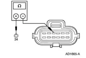
| D6 CHECK SOLENOID RESISTANCE AT SOLENOID | Yes GO to D7 . No INSTALL a new solenoid. CLEAR the DTCs. REPEAT the OBD Tests. |
|
|
| D7 CHECK SOLENOID FOR SHORT TO GROUND | Yes INSTALL a new solenoid. CLEAR the DTCs. REPEAT the OBD Tests. No REFER to Diagnosis By Symptom in this section for diagnosis of pressure concerns. |
|
|
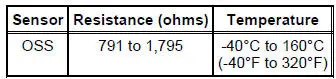
PINPOINT TEST E: OUTPUT SHAFT SPEED (OSS) SENSORS
| Test Step | Result / Action to Take |
| NOTE: Refer to the Output Shaft Speed (OSS) Sensor Harness Connector illustration preceding these pinpoint tests. | |
| E1 ELECTRONIC DIAGNOSTICS | Yes GO to E2 . No REPEAT procedure to ENTER PID. If vehicle did not enter PID, REFER to the Powertrain Control/Emissions Diagnosis (PC/ED) manual for diagnosis of PCM. |
|
|
| E2 DRIVE CYCLE TEST | Yes CLEAR all DTCs. ROAD TEST to verify if concern is still present. If concern is still present, REFER to Diagnosis By Symptom in this section. No If the OSS Speed PID does not increase and decrease with engine and vehicle speed, INSPECT for open or short in vehicle harness, sensor, a PCM concern, or internal hardware concern. If the sensor signal is erratic, INSPECT for intermittent concern in the internal/external harness, sensor, or connector. If the sensor signal is steady, GO to E3 . |
|
|
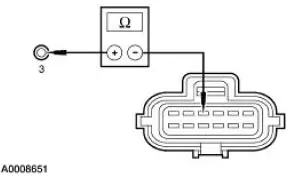
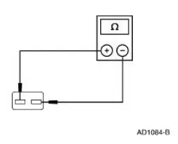
| E3 CHECK RESISTANCE OF OSS SENSOR | Yes REFER to Diagnosis By Symptom for concern diagnosis. No INSTALL a new OSS sensor. |
|
|
PINPOINT TEST F: SOLENOID MECHANICAL FAILURE
| Test Step | Result / Action to Take |
| NOTE: Repair all other DTCs before repairing the following DTCs: P1714, P1715, P1740. | |
| F1 ELECTRONIC DIAGNOSIS | Yes REPAIR the other DTCs first. CLEAR DTCs and CARRY OUT Transmission Drive Cycle Test. REPEAT Quick Test. No INSTALL a new solenoid and or body. REFER to the Diagnostic Trouble Code Charts in this section for code description. GO to F2 . |
|
|
| F2 TRANSMISSION DRIVE CYCLE TEST | Yes GO to F3 . No REFER to Diagnosis By Symptom in this section to diagnose shift concerns. |
|
|
| F3 RETRIEVE DTCS | Yes INSTALL a new PCM. REFER to Section. ROAD TEST and REPEAT Quick Test. No Testing completed. If a concern still exists, REFER to Diagnosis By Symptom in this section for concern diagnosis. |
|
|
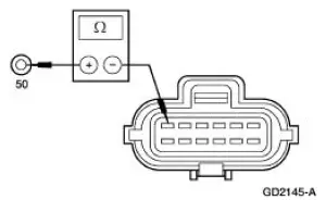
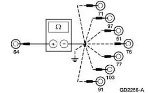
 Transmission Connector Layouts
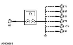
Transmission Vehicle Harness Connector
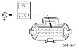
Transmission Internal Harness Connector
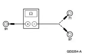
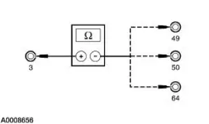
Digital Transmission Range (TR) Sensor Connector
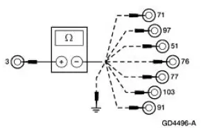
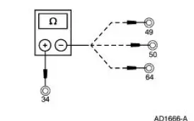
Output Shaft Speed (OSS) Sensor Harnes ...
 Special Testing Procedures
The special tests are designed to aid the technician in diagnosing the
hydraulic and mechanical portion
of the transmission.
Engine Idle Speed Check
Refer to the Powertrain Control/Emissions Diag ...
Other materials:
Air Bag Disposal - Passenger, Undeployed, Scrapped
Vehicle
Remote Deployment
WARNING: Always wear safety glasses when repairing an air bag
supplemental restraint
system (SRS) vehicle and when handling an air bag module or safety belt
retractor/pretensioner assembly. This will reduce the risk of injury in
t ...
Pinpoint Tests
The pinpoint tests are a step-by-step diagnostic process designed to
determine the cause of a condition. It may not always be necessary to follow a
pinpoint test to its conclusion. Carry out only the
steps necessary to correct the condition. Then, test the s ...
Intake Manifold Runner Control (IMRC) Actuator - 3.8L
Removal and Installation
1. Disconnect the battery ground cable. For additional information,
refer to Section.
2. Drain the cooling system. For additional information, refer to
Section.
3. Remove the upper intake manifold. For additional informat ...
