Ford Mustang (1999-2004) Service Manual: Transmission Connector Layouts
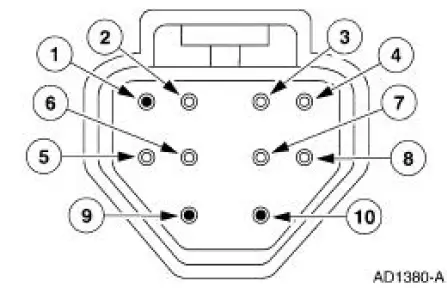
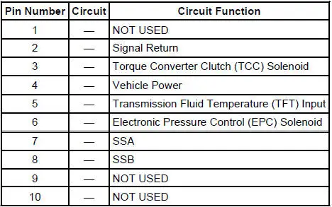
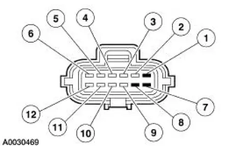
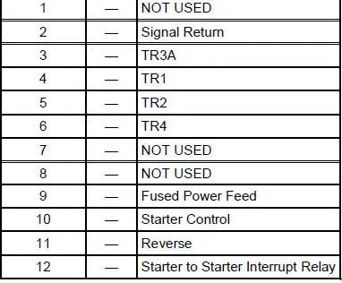
Transmission Vehicle Harness Connector
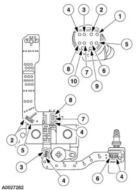
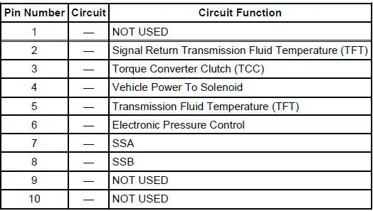
Transmission Internal Harness Connector
Digital Transmission Range (TR) Sensor Connector
![]()
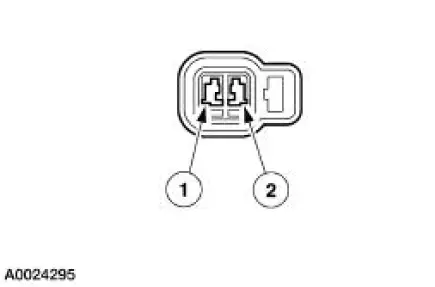
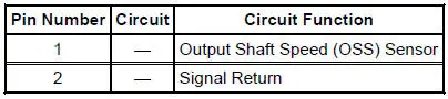
Output Shaft Speed (OSS) Sensor Harness Connector
Digital Transmission Range (TR) Sensor Diagnosis Chart
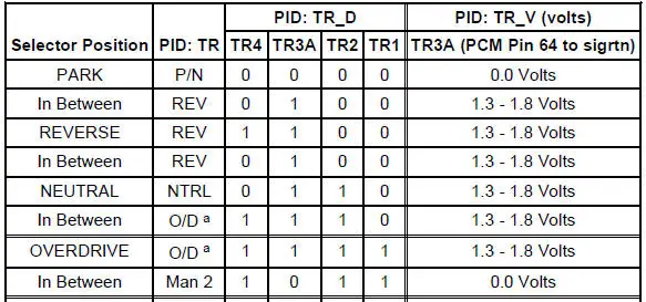
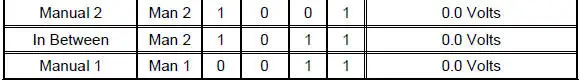
a - Will read "Drive" if O/D is canceled.
A. TR_V is the voltage at the PCM pin 64 (TR3A Circuit) to signal return.
B. "In Between" reading could be caused by a shift cable or digital TR sensor misaligned or a digital TR sensor circuit failure of TR1, TR2, TR3A, or TR4.
C. TR_D: 1= Open Digital TR switch, 0= Closed Digital TR switch.
D. EEC-V Control System Breakout Box Readings: Taken from PCM signal pins for TR1, TR2, TR3A, TR4 to signal return.
Voltages for TR1, TR2, TR4:
- 0 = 0.0 volts.
- 1 = 9.0 - 14.0 volts.
- Voltage for TR3A:
- 0 = 0.0 volts.
- 1 = 1.3 - 1.8 volts.
Wiggle Test Information For Open/Shorts
- TR4, TR3A, TR2, and TR1 are all closed in PARK. PARK is a good position to check for intermittent open circuits (with scan tool monitoring TR_D).
- TR4, TR3A, TR2, and TR1 are all open in OVERDRIVE, so OVERDRIVE is a good position to check for shorts to ground. To determine the shorted components while observing TR_D, unplug the TR and see if the short goes away. If the short is still present, unplug the transmission harness and see if the short goes away. If the short is still present, then the short is in the PCM or vehicle harness. Remove the suspect circuit(s) wire from the PCM vehicle harness. If the short is still present, then the PCM has an internal failure. Otherwise the failure is in the vehicle harness.
 Diagnostic Trouble Code Charts
Diagnostic Trouble Code Chart
Five
Digit
DTC
Component
Description
Condition
Symptom
Action
P0102
P0103
P1100
P1101
MAF
MAF concerns
MAF system has a
malfunction ...
 Pinpoint Tests - OSC Equipped Vehicles
Special Tool(s)
Breakout Box, EEC-V Control
System
418-049 (T94L-50-EEC-V) or
equivalent
MLP-TR Cable
418-F107 (007-00111) or
equivalent
Worldwide Diagnost ...
Other materials:
Subwoofer Speaker - Convertible
Removal and Installation
1. Remove the rear quarter trim panel. For additional information,
refer to Section .
2. Remove the subwoofer assembly.
1. Disconnect the electrical connectors.
2. Remove the screws.
3. Remove the subwoofer assemb ...
Transmission Case
Special Tool(s)
Handle
205-D055 (D81L-4000-A)
Installer, Bearing Cup
204-039 (T77F-1217-B)
Installer, Drive Pinion Bearing
Cup
205-054 (T71P-4616-A)
Installer, Rear Axle Oil Seal
205-155 (T80T-4000-Y)
...
Bulb
Removal and Installation
1. Remove the floor console. For additional information, refer to
Section.
2. Remove the bolts, then position the bezel upward.
3. Remove the bulb socket from the bezel.
4. Remove the bulb.
5. To install, reverse the removal ...
