Ford Mustang (1999-2004) Service Manual: Special Testing Procedures
The special tests are designed to aid the technician in diagnosing the hydraulic and mechanical portion of the transmission.
Engine Idle Speed Check
Refer to the Powertrain Control/Emissions Diagnosis (PC/ED) manual for diagnosis and testing of the engine idle speed.
Line Pressure Test
CAUTION: Carry out the line pressure test prior to carrying out the stall speed test. If the line pressure is low at stall, do not carry out stall speed test or further transmission damage will occur. Do not maintain WOT in any transmission range for more than five seconds.
This test verifies that the line pressure is within specification.
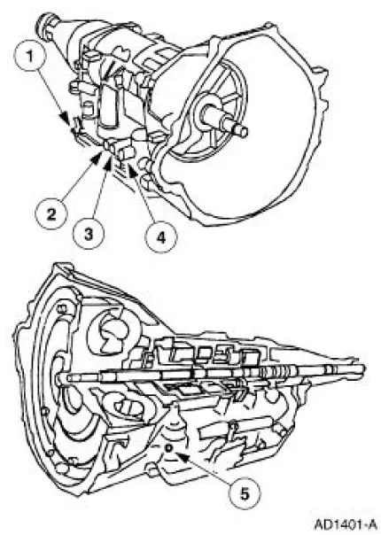
1. Connect pressure gauge to line pressure tap.
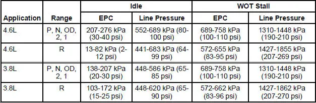
2. Start engine and check line pressures. Refer to the Line Pressure Chart to determine if line pressure is within specification.
Line Pressure Chart
Clutch Pressure Chart 3.8L
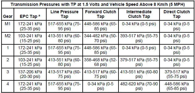
a - EPC readings will vary due to EEC strategy. These values are approximate pressures. Actual clutch apply pressures should be within 69-103 kPa (10-15 psi) of line pressure. For additional information on testing, refer to the Clutch Pressure Test in this section.
Clutch Pressure Chart 4.6L
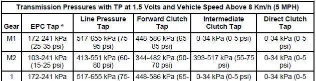
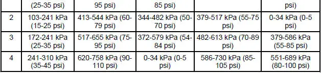
a - EPC readings will vary due to EEC strategy. These values are approximate pressures. Actual clutch apply pressures should be within 69-103 kPa (10-15 psi) of line pressure. For additional information on testing, refer to the Clutch Pressure Test in this section.
3. Place the ignition switch in the OFF position. If line pressure is not within specification, check EPC pressure.
4. Connect pressure gauge to EPC pressure tap.
5. Start engine and check EPC pressure. Use the line pressure chart for specifications.
6. If EPC pressure is not within specification, Go To Pinpoint Test E to diagnose EPC operation. If EPC operation is OK, see the line pressure diagnosis chart for line pressure concern causes.
Line Pressure Diagnosis Chart
| Test Results | Possible Source |
| High At Idle - In All Positions | Wiring Harnesses |
| Run Quick Test. Refer to the Powertrain Control/Emissions Diagnosis (PC/ED) manual. | |
| EPC Solenoid Main Regulator Valve |
|
| Low At Idle - In All Positions | Low Fluid Level |
| Control Bodies | |
| Leakage in Pump | |
| Damaged Gaskets on Separator Valve | |
| Damaged Separator Plate | |
| Restricted Inlet Filter | |
| Case Bolts | |
| Loose Main Control Valve Body | |
| EPC Solenoid O-Ring | |
| EPC Solenoid Bracket | |
| Case | |
| Sticking Main Regulator Valve Damaged Inlet Tube Seal on Inlet Filter |
|
| Low In Park Only | Valve Body Low/Reverse Servo |
| Low In Reverse Only | Separator Plate |
| Low/Reverse Servo or Valve Bodies Reverse Clutch |
|
| Low In Neutral Only | Valve Body |
| Low In Overdrive Only | Forward Clutch Valve Body |
| Low In 1st Position Only | Forward Clutch |
| Valve Body Low/Reverse Servo |
|
| Low In 2nd Only | Intermediate Clutch |
| Valve Bodies Forward Clutch |
Stall Speed Test
WARNING: Apply the parking brake firmly while carrying out each stall test.
CAUTION: Carry out line pressure test prior to carrying out stall test. If the line pressure is low at stall, do not carry out stall test or further transmission damage will occur.
The stall speed test checks:
- the torque converter clutch operation and installation.
- the holding ability of the forward clutch.
- the reverse clutch (the low-reverse bands).
- the planetary one-way clutch.
- the engine driveability.
Conduct this test with the engine coolant and transmission fluid at correct levels and at normal operating temperature.
Apply the parking brake firmly for each stall speed test.
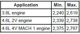
1. Find the specified stall rpm for the vehicle; see the stall speed diagnosis chart. Use a grease pencil to mark the rpm on the dial of a tachometer.
Stall Speed
2. Connect a tachometer to the engine.
3. NOTE: If the rpm recorded by the tachometer exceeds the maximum limits, release the accelerator pedal immediately because clutch or band slippage is indicated.
In each of the following ranges (D), 2, 1, R, press the accelerator pedal to the floor and hold it just long enough to let the engine get to wide open throttle (WOT). While making this test, do not hold the throttle open for more than 5 seconds at a time.
4. Note the results in each range.
5. After each range, move the shift control selector lever to NEUTRAL and run the engine at 1,000 rpm for about 15 seconds to cool the torque converter before making the next test.
6. Refer to the stall speed diagnosis chart for corrective actions.
Stall Speed Diagnosis Chart
| Selector Position | Stall Speeds High | Stall Speeds Low |
| (D) | Planetary One-Way Clutch | |
| (D), 2 and 1 | Forward Clutch or Intermediate Clutch | |
| (D), 2, 1 and R | Carry Out Pressure Test | Torque Converter Stator One-Way Clutch or Engine Driveability Concerns |
| R | Reverse Clutch or Low Reverse Band or Servo |
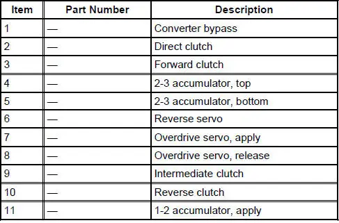
Air Pressure Tests
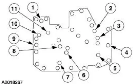
Transmission Air Test Plate
A no-drive condition can exist even with correct transmission fluid pressure because of inoperative clutches or bands. An erratic shift can be located through a series of checks by substituting air pressure for fluid pressure to determine the location of the malfunction.
Follow the procedure to determine the location of the inoperative clutch or band by introducing air pressure into the various test plate passages.
NOTE: Use only dry, regulated 276 kPa (40 psi) maximum air pressure.
Apply air to the appropriate passage(s). A dull thud should be felt or heard or movement could be observed when the clutch component applies. There should be no hissing sound when the component is applied.
Cover the vent hole in the test plate with a clean, lint-free shop towel to prevent spray when the air is applied. Plugging the vent hole during testing will result in inaccurate results.
1. Drain transmission fluid and remove the transmission fluid pan.
2. Remove the main control valve body.
3. Install transmission test plate and gasket. Tighten bolts to 10 Nm (89 lb-in).
4. NOTE: Do not apply air to the test plate vent hole.
Apply air to the appropriate clutch port (refer to the Transmission Air Test Plate illustration). A dull thud may be heard or movement felt when the component is applied or released. If clutch seals or check balls are leaking a hissing sound may be heard.
If the servos do not operate, disassemble, clean and inspect them to locate the source of the concern.
If air pressure applied to the clutch passages fails to operate a clutch, or operates clutches simultaneously, inspect the fluid passages in the case.
If air pressure applied to the accumulator fails to operate an accumulator, remove and inspect case passages and piston.
Clutch Pressure Test
The Clutch Pressure Test will diagnose a low-pressure condition or leakage in a clutch circuit. A difference of 103 kPa (15 psi) or more between the clutch pressure and line pressure will prevent a normal shift.
1. CAUTION: Pressure gauges affect the shift quality of the transmission. Care must be taken not to accelerate or decelerate rapidly. Possible transmission failure can result.
Attach 0-2068 kPa (0-300 psi) pressure gauges to the line pressure tap and the appropriate clutch pressure tap according to Band and Clutch Application Chart A&B. Gauges must be accurate enough to distinguish a 103 kPa (15 psi) difference. (If this test is done in conjunction with a control pressure test, pressure gauges will be attached to all pressure taps.) Have sufficient flexible hose available to read the gauges in the vehicle.
2. Drive the vehicle. When pressure is applied to the clutch, note the difference between the line pressure gauge and the corresponding clutch pressure gauge.
3. If the difference in pressures is less than 103 kPa (15 psi), the corresponding clutch circuit does not have a pressure loss. The gauges on the line pressure tap and appropriate clutch pressure tap can be switched to confirm that gauge calibration differences are not the cause.
4. If the difference is greater than 103 kPa (15 psi), there is a leak in the corresponding clutch pressure circuit. The gauges on the line pressure tap and clutch pressure tap can be switched to confirm that gauge calibration differences are not the cause. Carry out the appropriate procedure to correct the clutch leak problem.
 Pinpoint Tests - OSC Equipped Vehicles
Special Tool(s)
Breakout Box, EEC-V Control
System
418-049 (T94L-50-EEC-V) or
equivalent
MLP-TR Cable
418-F107 (007-00111) or
equivalent
Worldwide Diagnost ...
 Leakage Inspection
CAUTION: Do not try to stop the fluid leak by increasing the torque
beyond specifications.
This may cause damage to the case threads.
Check the fluid filler tube connection at the transmission ca ...
Other materials:
Accelerator Pedal and Shaft
Removal and Installation
1. Push the accelerator cable nylon bushing out of the accelerator pedal and
shaft arm.
2. Remove the accelerator pedal and shaft.
Remove the nuts.
Remove the accelerator pedal and shaft.
3. To install, reverse the removal pro ...
Removal
1. Disconnect the battery ground cable. For additional information, refer
to Section.
2. Drain the engine cooling system. For additional information, refer to
Section .
3. Remove the crankshaft pulley. For additional information, refer to
Crankshaft ...
Transmission (Removal)
1. Remove the gearshift lever knob.
2. Remove the console panel gearshift plate. Disconnect the cigar lighter
electrical connector, then
lift the gearshift lever boot over the gearshift lever.
3. Remove the bolts and the upper gearshift lever.
4. Remove ...
