Ford Mustang (1999-2004) Service Manual: Principles of Operation
There are four main principles involved with the basic theory of operation:
- heat transfer
- latent heat of vaporization
- relative humidity
- effects of pressure
Heat Transfer
If two substances of different temperature are placed near each other, the heat in the warmer substance will transfer to the colder substance.
Latent Heat of Vaporization
When a liquid boils (converts to a gas), it absorbs heat without raising the temperature of the resulting gas. When the gas condenses (reverts back to a liquid), it gives off heat without lowering the temperature of the resulting liquid.
Relative Humidity
The amount of moisture (water vapor content) that the air can hold is directly related to the air temperature. The more heat there is in the air, the more moisture the air can hold. The lower the moisture content in the air, the more comfortable you feel. Removing moisture from the air lowers its relative humidity and improves personal comfort.
Effects of Pressure on Boiling or Condensation
As the pressure is increased on a liquid, the temperature at which the liquid boils (converts to a gas) also increases. Conversely, when the pressure on a liquid is reduced, its boiling point is also reduced.
When in the gas state, an increase in pressure causes an increase in temperature, while a decrease in pressure will decrease the temperature of the gas.
Compressor Anti-Slugging Strategy
Liquid refrigerant may accumulate in the A/C compressor under certain conditions. To alleviate damage to the A/C compressor, compressor anti-slugging strategy (CASS) is utilized.
CASS is initiated only under specific conditions:
- the ignition is off for more than 8 hours
- the ambient temperature is above -4?C (25?F)
- battery voltage is above 8.5 volts during engine cranking
When these conditions are present, the powertrain control module (PCM) will activate the A/C control relay prior to cranking of the engine. The A/C control relay engages the A/C compressor for approximately 4-15 A/C compressor revolutions or a maximum of 2 seconds (depending upon vehicle application), allowing the liquid refrigerant to be pushed from the A/C compressor. CASS is initiated by the PCM regardless of the function selector switch position or the EATC system settings.
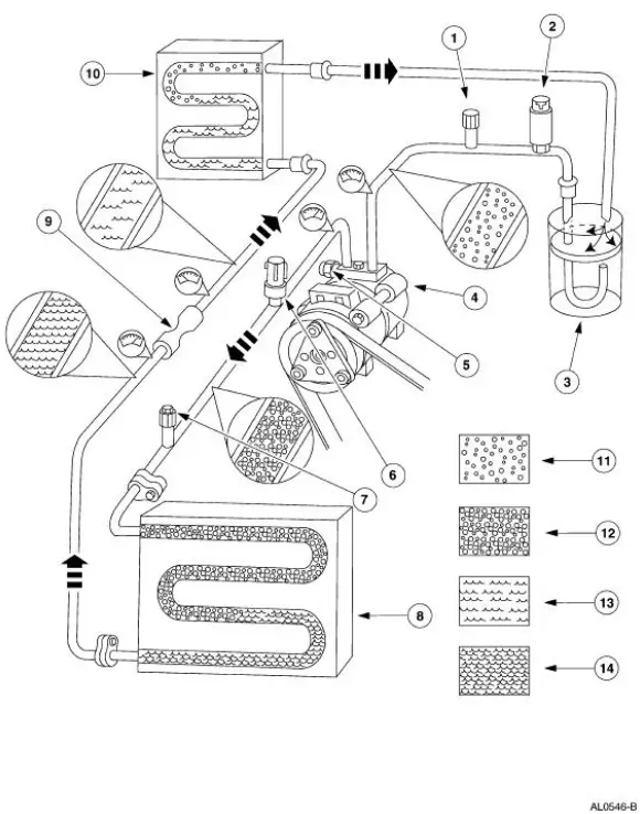
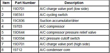
The Refrigerant Cycle
During stabilized conditions (air conditioning system shut down), the refrigerant is in a vaporized state and pressures are equal throughout the system. When the A/C compressor (19703) is in operation, it increases pressure on the refrigerant vapor, raising its temperature. The high-pressure and hightemperature vapor is then released into the top of the A/C condenser core (19712).
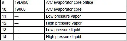
The A/C condenser core, being close to ambient temperature, causes the refrigerant vapor to condense into a liquid when heat is removed from the refrigerant by ambient air passing over the fins and tubing. The now liquid refrigerant, still at high pressure, exits from the bottom of the A/C condenser core and enters the inlet side of the A/C evaporator core orifice (19D990).
The A/C evaporator core orifice is the restriction in the refrigerant system that creates the high pressure buildup upstream of the A/C evaporator core (19860) and separates the high and low pressure sides of the A/C system. As the liquid refrigerant leaves this restriction, its pressure and boiling point are reduced.
The liquid refrigerant is now at its lowest pressure and temperature. As it passes through the A/C evaporator core, it absorbs heat from the passenger compartment airflow passing over the plate/fin sections of the A/C evaporator core. This addition of heat causes the refrigerant to boil (convert to a gas). The now cooler passenger compartment air can no longer support the same humidity level of the warmer air and this excess moisture condenses on the exterior of the evaporator coils and fins and drains outside the vehicle.
The suction accumulator/drier (19C836) is designed to remove moisture from the refrigerant and to prevent any liquid refrigerant that may not have been vaporized in the A/C evaporator core from reaching the A/C compressor. The A/C compressor is designed to pump refrigerant vapor only, as liquid refrigerant will not compress and can damage the A/C compressor.
The refrigerant cycle is now repeated with the A/C compressor again increasing the pressure and temperature of the refrigerant.
The A/C cycling switch (19E561) interrupts compressor operation before the external temperature of the A/C evaporator core gets low enough to cause the condensed water vapor (excess humidity) to turn to ice. It does this by monitoring low side line pressure. It is known that a refrigerant pressure of approximately 210 kPa (30 psi) will yield an operating temperature of 0C (32F). The A/C cycling switch controls system operation in an effort to maintain this temperature.
The high side line pressure is also monitored so that the A/C compressor operation can be interrupted if system pressure becomes too high.
The A/C compressor pressure relief valve (19D644) will open and vent refrigerant to relieve unusually high system pressure.
Clutch Cycling Orifice Tube Type Refrigerant System
 Climate Control System (Description and Operation)
WARNING: To avoid accidental deployment and possible injury, the air
bag system
backup power supply must be depleted before repairing any climate control
components. To
deplete the backup power supp ...
 System Air Flow Description
MAX A/C
When MAX A/C is selected:
The air inlet door vacuum control motor is at full vacuum, closing
off outside air and admitting
only recirculated air.
The panel/defrost door vacuum cont ...
Other materials:
Supercharger Cooling (Diagnosis and Testing)
Special Tool(s)
Pressure Test Kit
014-R1072 or equivalent
Battery/Antifreeze Tester
014-R1060 or equivalent
Material
Item
Specification
Motorcraft Premium
Engine Coolant
VC-4-A (in Oregon
VC-5, in Canada
C ...
Brake System (Diagnosis and Testing)
Refer to Wiring Diagrams Cell 60, Instrument Cluster for schematic and
connector information.
Refer to Wiring Diagrams Cell 97, Daytime Running Lamps for schematic and
connector information.
Special Tool(s)
73 Digital Multimeter
105-R0051 or Equiva ...
Handles, Locks, Latches and Mechanisms
General Specifications
Torque Specifications
LOCK REPAIR/REPLACEMENT SPECIFICATIONS
...
