Ford Mustang (1999-2004) Service Manual: Removal
1. Remove the A/C compressor (19703). For additional information, refer to Air Conditioning (A/C) Compressor-3.8L or Air Conditioning (A/C) Compressor-4.6L in this section.
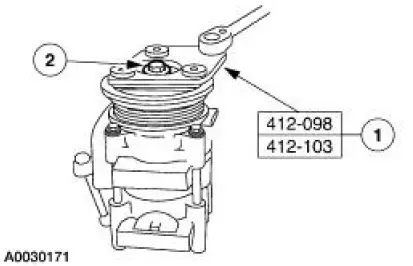
2. Remove the bolt.
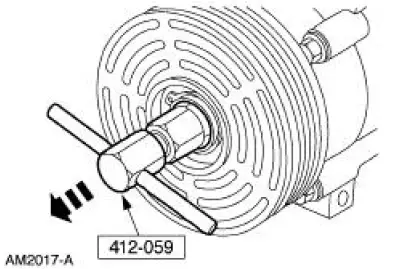
1. Hold the A/C disc and hub assembly (19D786) with the special tool.
2. Remove the bolt.
3. Remove the A/C disc and hub assembly and spacer (19D648).
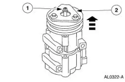
1. Thread an 8 x 1.25 mm (0.05 in) bolt into the A/C disc and hub assembly to force it from the compressor shaft.
2. Lift the A/C disc and hub assembly and spacer from the compressor shaft.
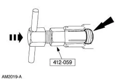
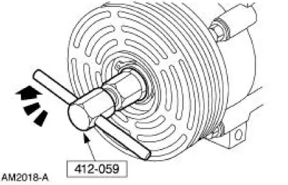
4. Using the special tool, remove the shaft seal felt from the nose of the A/C compressor.
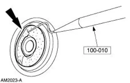
5. Clean the compressor nose area.
6. Insert the tip of the special tool into one of the snap ring eyes.
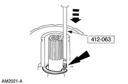
7. Rotate the special tool to position the tool tip and the snap ring eye closest to the A/C compressor shaft.
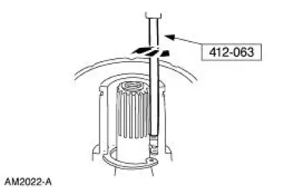
8. Pull the special tool up quickly while keeping the tool shaft against the side of the nose opening and remove the snap ring.
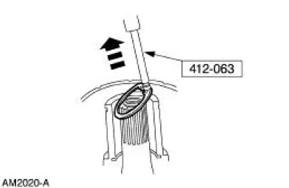
9. Engage the special tool into the inside diameter of the shaft seal.
10. Turn the tool handle clockwise to expand the tool tip inside the shaft seal.
11. Pull the seal from the A/C compressor.
 Air Conditioning (A/C) Compressor Shaft Seal
Special Tool(s)
Holding Fixture, Compressor
Clutch (3.8L vehicles)
412-098 (T94P-19703-AH)
Holding Fixture, Compressor
Clutch (4.6L vehicles)
412-103 (T95L-19703-AH)
...
 Installation
1. CAUTION: To prevent refrigerant system contamination, do not allow
dirt or other
foreign materials to enter the A/C compressor.
Clean the A/C compressor nose area.
2. Place the shaft seal on the s ...
Other materials:
Pinpoint Test K: LFC 35/DTC B1935 - Passenger Air Bag Circuit Resistance
Low
Normal Operation
The restraints control module (RCM) monitors the resistance of the
passenger air bag ignitor by
measuring the resistance between pins 6 and 7. If the RCM detects low
resistance between these
pins, it will store a diagnostic trouble code ...
Installation
All vehicles
1. Using the special tools, install the crankshaft rear oil seal.
Lubricate the oil seal using clean engine oil.
2. Using the special tool, install the crankshaft oil slinger.
Manual transmission vehicles
3. Install the flywheel. For additi ...
Spring Codes
The spring code portion of the vehicle certification (VC) label identifies
both the front and rear springs.
The first letter/number indicates the front spring code. The second
letter/number indicates the rear
spring code.
Front springs - base part numbe ...
