Ford Mustang (1999-2004) Service Manual: Removal
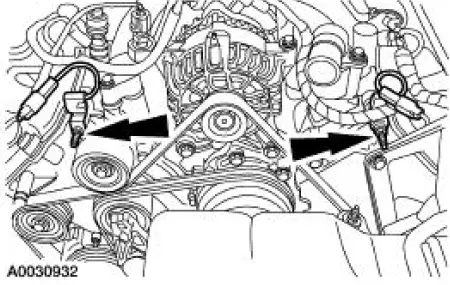
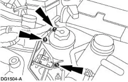
1. Remove the nuts and position the radio ignition interference capacitors aside.
2. Remove the valve covers. For additional information, refer to Valve Cover RH and Valve Cover LH in this section.
3. Remove the cooling fan.
4. Remove the accessory drive belt. For additional information, refer to Section.
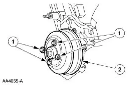
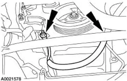
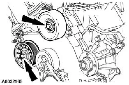
5. Remove bolts (1) and the water pump pulley (2).
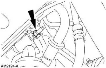
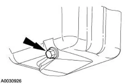
6. Remove the nut and position the A/C muffler aside.
7. Raise and support the vehicle. For additional information, refer to Section.
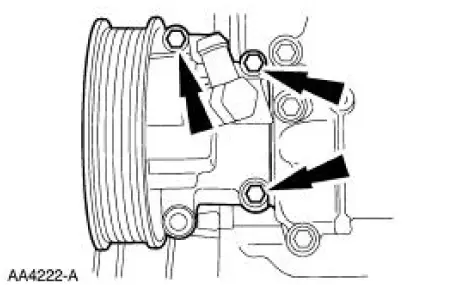
8. Remove the bolts and position the power steering pump aside.
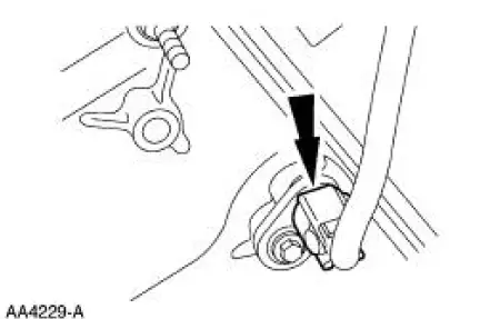
9. Disconnect the crankshaft position (CKP) sensor electrical connector.
10. Drain the engine oil.
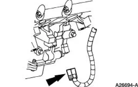
11. Remove the two support nuts and position the battery cable aside.
12. Remove the crankshaft front oil seal. For additional information, refer to Crankshaft Front Oil Seal in this section.
13. Remove the front oil pan bolts.
14. Lower the vehicle.
15. Remove the bolts and position the power steering reservoir aside.
16. Disconnect the camshaft position (CMP) sensor electrical connector.
17. Remove the bolts and the belt idler pulleys.
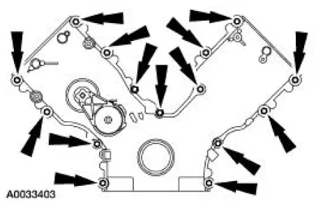
18. Remove the engine front cover bolts and the studs.
- Discard the gaskets. Clean and inspect the sealing surfaces.
 Engine Front Cover
Material
Item
Specification
Silicone Gasket and Sealant
F7AZ-19554-EA or equivalent
WSE-M4G323-
A4
Super Premium SAE 5W-20
Motor Oil
XO-5W20-QSP or equivalent
WSS-M2C153 ...
 Installation
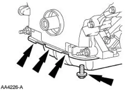
1. Apply silicone gasket and sealant in the locations shown.
2. Install the engine front cover.
3. Install the belt idler pulleys and the bolts.
4. Connect the CMP sensor electrical conn ...
Other materials:
Parking brake
WARNING: If the parking brake is fully released, but the brake
warning lamp remains illuminated, the brakes may not be
working properly. See your authorized dealer as soon as possible.
WARNING: Always set the parking brake fully and make sure
that the transmis ...
Water Pump - 4.6L(2V) and 4.6L(4V)
Material
Item
Specification
Motorcraft Premium Gold
Engine Coolant
VC-7-A (in Oregon VC-7-B)
(yellow color)
WSS-M97B51-
A1
Removal and Installation
Mach I
1. Remove the air intake scoop. For additional information, refer to Section.
...
Principles of Operation
There are four main principles involved with the basic theory of
operation:
heat transfer
latent heat of vaporization
relative humidity
effects of pressure
Heat Transfer
If two substances of different temperature are placed near each other,
t ...
