Ford Mustang (1999-2004) Service Manual: Spring Codes
The spring code portion of the vehicle certification (VC) label identifies both the front and rear springs.
The first letter/number indicates the front spring code. The second letter/number indicates the rear spring code.
- Front springs - base part number - 5310 (RH/LH)
- Rear springs - base part number - 5560 (RH/LH)
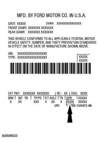
Powertrain Calibration Information
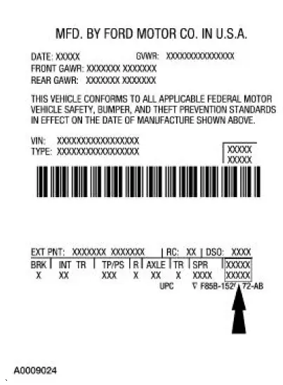
NOTE: Powertrain calibration information is limited to a maximum of five characters per line on the Vehicle Certification Label. Because of this, calibration identification consisting of more than five characters will wrap to the second line on the VC label.
Powertrain calibration information is printed in the lower right corner of the Vehicle Certification Label.
Only the base calibration information is printed. Revision levels will not appear, however, this information can be found in the On Line Automotive Service Information System (OASIS). For the current model year, Ford Motor Company is using three different protocols which describe powertrain base calibration. These protocols are designed to provide worldwide standardization for vehicle calibration. If the electronic calibration strategy has been used since 1998 and carried into the current model year, protocol 1 will be used. Refer to Protocol 1 below. If the electronic calibration strategy has been used since 1999 and is carried into the current model year, protocol 2 will be used. Refer to Protocol 2 below. For new electronic calibration strategies introduced since the 2000 model year, use protocol 3. Refer to Protocol 3 below.
Protocol 1
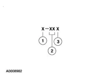
| Item | Description |
| 1 | Model year (model year in which calibration strategy was first introduced) |
| 2 | Engine code |
| 3 | Engine revision level |
Protocol 2
| Item | Description |
| 1 | Model year (model year in which calibration strategy was first introduced) |
| 2 | Engine code |
| 3 | Transmission code |
| 4 | Emission standard (designates the specific country emission standard) |
| 5 | Design level (design level assigned to the engine) |
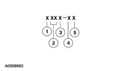
Protocol 3
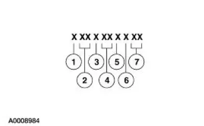
| Item | Description |
| 1 | Model year (model year in which calibration strategy was first introduced) |
| 2 | Vehicle code |
| 3 | Transmission code |
| 4 | Unique calibration (designates different hardware to similar vehicles). Example: tires, drive ratios, etc. |
| 5 | Fleet code (describes fleet to which the vehicle belongs). Example: 6 - evaporative emissions |
| 6 | Certification region (lead region where multiple regions are
included in one calibration). Example: A - U.S. federal |
| 7 | Revision level (will advance as revisions occur). Not printed on label |
Protocol 3
The following offers a more detailed explanation of the coding strategy used for protocol 3.
Model Year
- Y - 2000
- 1 - 2001
- 2 - 2002
- 3 - 2003
Vehicle Line
- ZE - Mustang
Transmission
- 1 - Automatic transmission
- 2 - Manual transmission
 Interior Trim Codes
The interior trim codes are listed below. The first letter/number is for the
interior fabric. The second
letter is for the interior color.
9 - Quantum/Rhodes cloth (base coupe)
A - Link weave cl ...
 Unique Calibration
The Emissions/CAFE/CO2 Compliance Department is responsible for assigning
these calibration
numbers. Unique calibration identifications are assigned to cover similar
vehicles to differentiate tires, ...
Other materials:
Installation
1. Clean the A/C disc and field coil and pulley mounting surfaces.
2. CAUTION: Do not use air tools. The A/C clutch field coil can be easily
damaged.
Install the A/C clutch field coil.
1. Place the A/C clutch field coil on the A/C compressor with the A/C
...
Valve Stem to Valve Guide Clearance
Special Tool(s)
Dial Indicator Gauge with
Holding Fixture
100-002 (TOOL-4201-C) or
equivalent
Clearance Gauge, Valve Guide
303-004 (TOOL-6505-E) or
equivalent
NOTE: Valve stem diameter must be within specifications before
checkin ...
Underbody Misalignment Check
Underbody Dimensions
1. Underbody dimensions tolerances are +- 3.175 mm (0.125 in). Reference
dimensions are not
controlled dimensions. Reference points are +- 4.76 mm (0.1875 in). All underbody
dimensions
are detailed to the centerline of existin ...
