Ford Mustang (1999-2004) Service Manual: Weld Nut Repair - Missing Weld Nut, Restraints Control Module (RCM)
WARNING: To avoid accidental deployment and possible personal injury, the backup power supply must be depleted before repairing or replacing any front or side air bag supplemental restraint system (SRS) components and before servicing, replacing, adjusting or striking components near the front or side air bag sensors, such as doors, instrument panel, console, door latches, strikers, seats and hood latches.
Please refer to the appropriate vehicle shop manual to determine location of the front air bag sensors.
The side air bag sensors are located at or near the base of the B-pillar.
To deplete the backup power supply energy, disconnect the battery ground cable and wait at least one minute. Be sure to disconnect auxiliary batteries and power supplies (if equipped).
NOTE: There are two procedures to repair a vehicle having missing restraints control module attaching weld nut(s). Read both procedures before proceeding with the repair.
NOTE: If two or more weld nuts are missing, do not install the "J" nuts as outlined in Weld Nut Repair - "J" Nut, Restraints Control Module (RCM). Weld nuts must be installed as outlined in this procedure.
NOTE: Radiator support repair shown, others are similar.
1. Obtain a 6 mm (0.24 in) weld nut (part number N806285-S190).
2. Obtain a 6 mm (0.24 in) grounding screw (part number N806327-S190).
3. Route a sufficient length of copper welding wire through the weld nut clearance hole and back out an adjacent access hole.
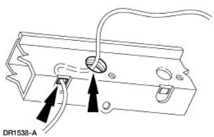
4. Feed the copper welding wire through the weld nut, then through a standard flatwasher.
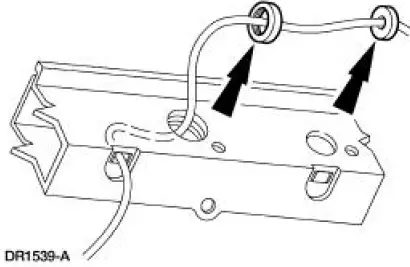
5. Secure the flatwasher so that it cannot be pulled off the end of the copper welding wire.
6. Pull the copper welding wire back through the clearance hole, allowing the weld nut and flatwasher to follow the copper welding wire through.
7. Position the weld nut to the weld nut clearance hole, firmly pulling on the copper welding wire allowing the secured flatwasher to hold the weld nut in position.
8. Holding the weld nut securely in place and using a MIG welder, weld in four places around the edge of the weld nut.
9. Metal finish as required.
10. Verify the nut is securely in place.
11. Install the crash sensor.
12. Tighten the attaching screws to specification. For additional information, refer to Torque Specifications in this section.
 Weld Nut Repair - "J" Nut, Restraints Control
Module
(RCM)
Weld Nut Repair - "J" Nut, Restraints Control
Module
(RCM)
WARNING: To avoid accidental deployment and possible personal
injury, the backup
power supply must be depleted before repairing or replacing any front or
side air bag
supplemental restraint ...
 Weld Nut Repair - Stripped Weld Nut, Restraints
Control
Module (RCM)
Weld Nut Repair - Stripped Weld Nut, Restraints
Control
Module (RCM)
WARNING: To avoid accidental deployment and possible personal
injury, the backup
power supply must be depleted before repairing or replacing any front or
side air bag
supplemental restraint ...
Other materials:
Cylinder Heads (Installation)
Special Tool(s)
Installer, Crankshaft Vibration
Damper
303-102 (T74P-6316-B)
Installer, Front Cover Oil Seal
303-335 (T88T-6701-A)
Holding Tool, Crankshaft
303-448 (T93P-6303-A)
Spreader Bar
303-D089 (D9 ...
Air Bag Disposal - Passenger, Undeployed, Scrapped
Vehicle
Remote Deployment
WARNING: Always wear safety glasses when repairing an air bag
supplemental restraint
system (SRS) vehicle and when handling an air bag module or safety belt
retractor/pretensioner assembly. This will reduce the risk of injury in
t ...
Checks and Services
Certain basic maintenance checks and inspections should be carried out at
specified intervals. Any
recognized adverse condition should be corrected as soon as possible.
Maximum Oil Change Interval (Normal Schedule)
8,000 km (5,000 miles) or 6 months, whiche ...
