Ford Mustang (1999-2004) Service Manual: Charge Air Cooler
Material
| Item | Specification |
| Silicone Gasket and Sealant F7AZ-19554-EA or equivalent | WSE-M4G323-EA |
Removal and Installation
1. Drain the supercharger coolant. For additional information, refer to Section.
2. Release the fuel pressure. For additional information, refer to Section.
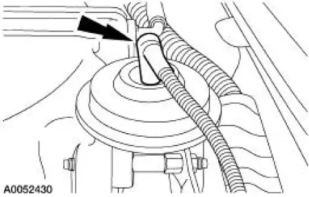
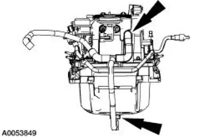
3. Disconnect the supercharger degas hose.
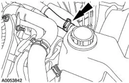
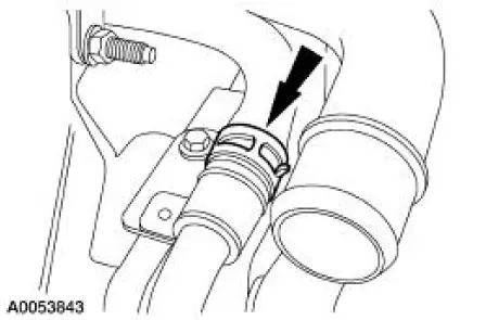
4. Disconnect the coolant hose.
5. Remove the supercharger belt. For additional information, refer to Section.
6. Remove the air cleaner outlet tube. For additional information, refer to Section.
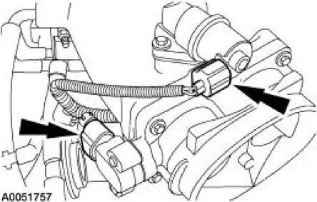
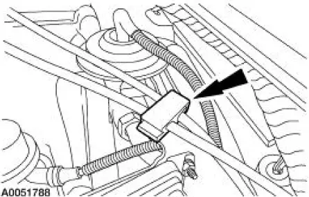
7. Disconnect the throttle position (TP) sensor and the idle air control (IAC) valve electrical connectors.
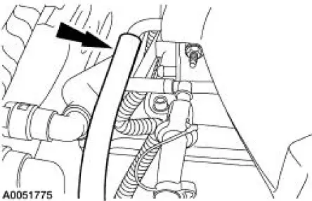
8. Disconnect the vacuum hose.
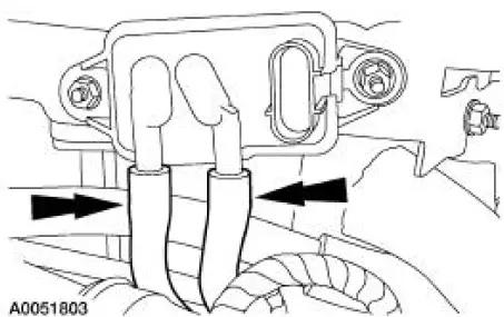
9. Disconnect the fuel supply spring lock coupler.
10. Disconnect the accelerator controls.
- Disconnect the accelerator cable.
- If equipped, disconnect the speed control cable.
11. Remove the accelerator cable bracket bolts.
12. Remove the throttle body and spacer assembly.
13. Release the clip and position the accelerator cable bracket and the cables aside.
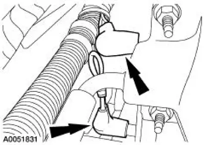
14. Disconnect the electrical connectors from the fuel pulse damper, EGR vacuum regulator solenoid, supercharger bypass vacuum solenoid, and the differential pressure feedback EGR system.
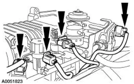
15. Disconnect the vacuum hoses from the differential pressure feedback EGR system.
16. Disconnect the vacuum hoses from the supercharger bypass vacuum solenoid, and the actuator.
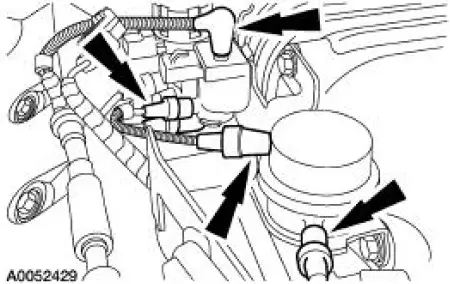
17. Disconnect the vacuum hoses from the fuel pulse damper and the EGR vacuum regulator solenoid.
18. Disconnect the vacuum hose from the EGR valv
19. Disconnect the vacuum hoses at the back of the supercharger and position the vacuum harness aside.
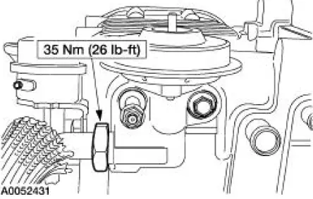
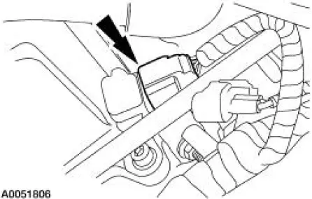
20. Remove the vacuum accessory bracket mounting nut.
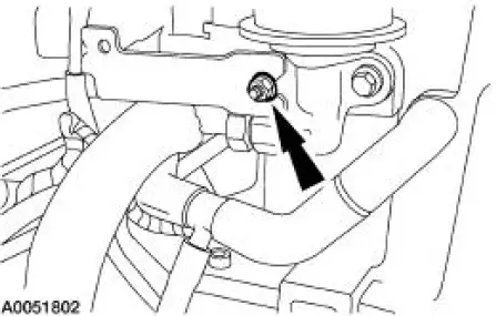
21. Remove the mounting bolts, and the vacuum accessory bracket.
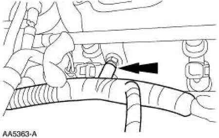
22. Disconnect the exhaust manifold to EGR valve tube.
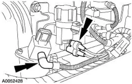
23. Disconnect the barometric pressure (BARO) sensor electrical connector.
24. Disconnect the positive crankcase ventilation (PCV) hose.
25. Separate the fuel charging wiring harness from the fuel injection supply manifold in four places and position the harness aside.
26. Remove the ten bolts, the intake manifold, supercharger and fuel supply manifold as an assembly.
27. Disconnect and remove the PCV hoses.
28. Remove the coolant supply and return manifold.
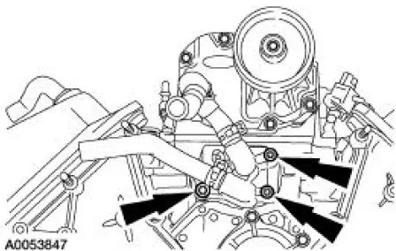
29. Remove the coolant supply and return tubes and seals.
29. Remove the coolant supply and return tubes and seals.
31. Remove the fuel supply manifold and fuel injectors as an assembly.
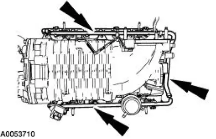
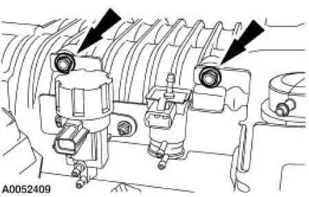
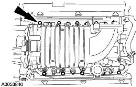
32. Remove the bolts, the supercharger and charge air cooler (CAC) assembly.
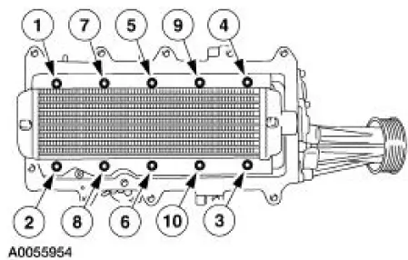
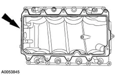
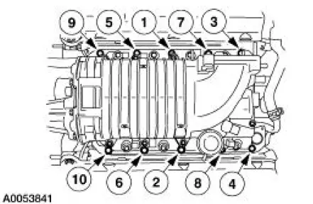
33. Remove the bolts and the CAC in the sequence shown.
34. Inspect the CAC plenum gasket and install a new gasket if necessary.
35. To install, reverse the removal procedure 36. Apply a bead of sealant in the areas shown on the supercharger flange between the CAC and the supercharger.

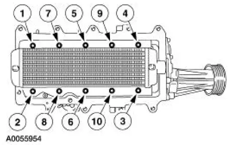
37. NOTE: Once the torque procedure has been started, final tightening must be finished within five minutes maximum.
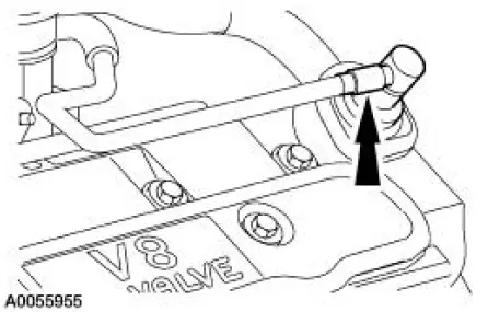
Tighten the CAC bolts in the sequence shown in two stages.
1. Tighten to 2 Nm (18 lb-in).
2. Tighten to 6 Nm (53 lb-in).
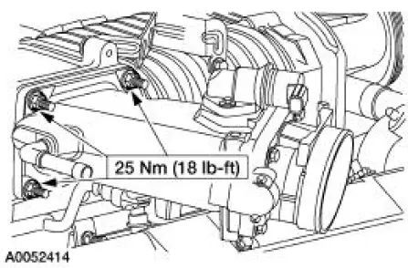
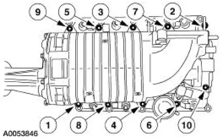
38. Tighten the supercharger and CAC cooler assembly-to-lower intake manifold bolts in the sequence shown in three stages.
1. Tighten to 2 Nm (18 lb-in).
2. Tighten to 25 Nm (18 lb-ft).
3. Tighten an additional 90 degrees.
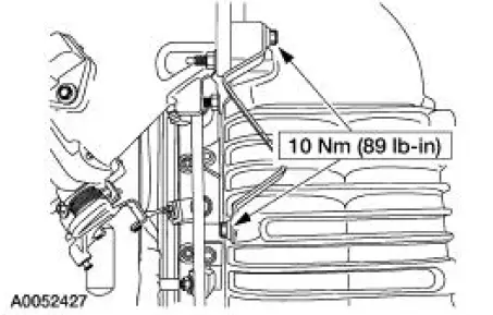
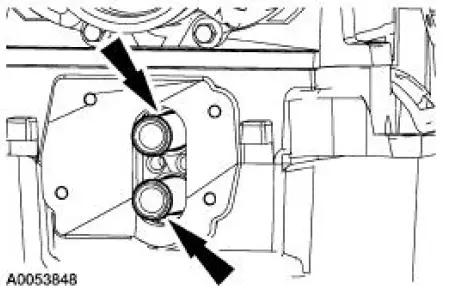
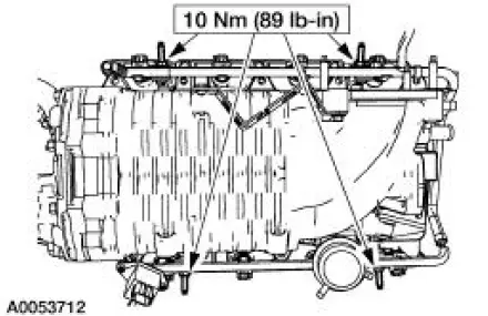
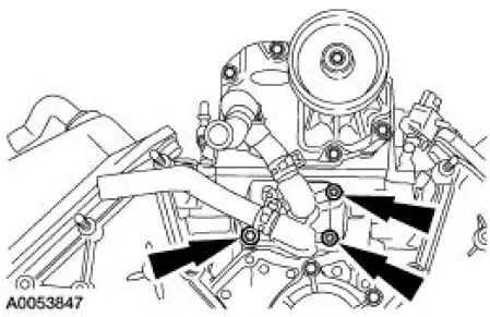
39. Tighten the coolant supply and return manifold in two stages.
1. Tighten to 10 Nm (89 lb-ft).
2. Tighten an additional 90 degrees.
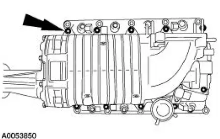
40. NOTE: Inspect the intake manifold gaskets and install new gaskets, if necessary.
Tighten the lower intake manifold bolts in the sequence shown.
41. Fill and bleed the supercharger cooling system.
 Air Intake Scoop Bracket
Removal and Installation
1. Remove the air intake scoop. For additional information, refer to Air
Intake Scoop in this section.
2. Remove the air intake scoop bracket nut at the throttle body.
...
 Evaporative Emissions
General Specifications
Torque Specifications
...
Other materials:
Installation
1. CAUTION: Install the brake pads in full axle sets. Do not
install new brake pads on
only one side of vehicle.
Install the new slipper and brake pads.
2. Position the caliper on the anchor plate and install the bolts.
3. Install the wheel and tire ...
Component Tests
Battery-Load Test
1. With the engine running, turn the A/C on, the blower motor on high
speed and the headlamps
on high beam.
2. Increase the engine speed to approximately 2,000 rpm. The voltage
should increase a minimum
of 0.5 volt above the ba ...
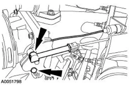
Spindle
Special Tool(s)
Tie-Rod End Remover
211-001 (TOOL-3290-D) or
Equivalent
Removal
CAUTION: Suspension fasteners are critical parts because they affect
performance of vital
components and systems and their failure can result in major service expen ...
