Ford Mustang (1999-2004) Service Manual: Charging System (Diagnosis and Testing)
Refer to Wiring Diagrams Cell 12 , Charging System for schematic and connector information.
Special Tool(s)
 |
73III Automotive Meter 105-R0057 or equivalent |
 |
SABRE Premium Battery and Electrical System Tester 010-00736 or equivalent |
Principles of Operation
 Charging System (Description and Operation)
The charging system is a negative ground system consisting of the
following:
generator
internal voltage regulator
charging system warning indicator
storage battery
necessary wirin ...
 Functionality
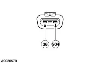
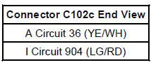
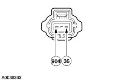
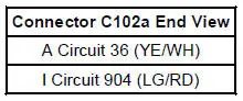
With the ignition switch in the RUN position, voltage is applied
through the warning indicator I circuit
904 (LG/RD) to the voltage regulator. This turns the regulator on,
allowing current to ...
Other materials:
Cable and Bracket
Removal
1. Raise the vehicle on a hoist. For additional information, refer to
Section.
2. Remove the cable shift from the shifter lever and bracket and discard
the clip.
3. Remove the bolt from the cable.
4. Remove the bolt from the cable.
5. ...
Spindle
Special Tool(s)
Tie-Rod End Remover
211-001 (TOOL-3290-D) or
Equivalent
Removal
CAUTION: Suspension fasteners are critical parts because they affect
performance of vital
components and systems and their failure can result in major service expen ...
Headlamps
Refer to Wiring Diagrams Cell 85 , Headlamps for schematic and
connector information.
Special Tool(s)
73III Automotive Meter or
equivalent
105-R0057
Inspection and Verification
1. Verify the customer concern by operating the headlamps. ...
