Ford Mustang (1999-2004) Service Manual: Bypass Tube - 3.8L
Material
| Item | Specification |
| Motorcraft Premium Gold Engine Coolant VC-7-A (in Oregon VC-7-B) (yellow color) | WSS-M97B51- A1 |
Removal and Installation
1. Drain the engine coolant. For additional information, refer to Cooling System Draining, Filling and Bleeding in this section.
2. Remove the upper intake manifold. For additional information, refer to Section.
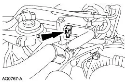
3. Remove the bypass hose from the bypass tube.
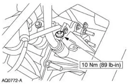
4. Remove the bolt and remove the bypass tube from the coolant pump.
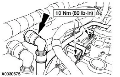
5. Disconnect the quick connect fitting and remove the bracket bolts and the bypass tube.
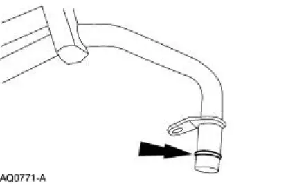
6. Install a new O-ring seal on the coolant bypass tube.
7. CAUTION: Do not cut the O-ring seal during tube installation or engine coolant leakage may occur.
Clean the O-ring sealing surface on the cylinder heads and lubricate the O-ring seal. Use premium engine coolant.
8. To install, reverse the removal procedure.

 Thermostat - 4.6L(4V)
Material
Item
Specification
Motorcraft Premium Gold
Engine Coolant
VC-7-A (in Oregon VC-7-B)
(yellow color)
WSS-M97B51-
A1
Removal and Installation
1. With the vehicle in ne ...
 Bypass Tube - Cobra
Material
Item
Specification
Motorcraft Premium Gold
Engine Coolant
VC-7-A (in Oregon VC-7-B)
(yellow color)
WSS-M97B51-
A1
Removal and Installation
1. Drain the engine coola ...
Other materials:
Index Card
Place an index card or a piece of paper between the weatherstrip and the
sealing surface, then close
the door. Slowly withdraw the index card or paper after the door is closed and
check the amount of
pressure on the weatherstrip. There should be a medium amo ...
Rear View Mirrors
Torque Specifications
Rear View Mirrors
The rear view mirror system consists of the following components:
exterior rear view mirror
exterior rear view mirror control
exterior rear view mirror glass
exterior rear view mirror motor
interior ...
Hill start assist
WARNING: The hill start assist feature does not replace the
parking brake. When you leave the vehicle, always apply the
parking brake and shift the transmission into position P for automatic
transmission or position 1 for manual transmissions.
WARNING: You mus ...
