Ford Mustang (1999-2004) Service Manual: Component Tests
Battery-Load Test
1. With the engine running, turn the A/C on, the blower motor on high speed and the headlamps on high beam.
2. Increase the engine speed to approximately 2,000 rpm. The voltage should increase a minimum of 0.5 volt above the base voltage.
- If the voltage does not increase as specified, carry out the
Generator On-Vehicle Tests.
For additional information, refer to Generator On-Vehicle Tests in this section.
- If the voltage increases as specified, the charging system is operating normally.
Battery-Drain Tests
NOTE: No production vehicle should have more than a 50 mA (0.050 amp) continuous draw.
Check for current drains on the battery in excess of 50 milliamps (0.050 amp) with all the electrical accessories off and the vehicle at rest. Current drains can be tested with the following procedure:
WARNING: Do not attempt this test on a lead-acid battery that has recently been recharged. Explosive gases can cause personal injury.
CAUTION: To prevent damage to the meter, do not crank the engine or operate accessories that draw more than 10A.
NOTE: Many modules draw 10 mA (0.010 amp) or more continuously.
NOTE: Use an in-line ammeter between the battery positive or negative post and its respective cable.
NOTE: Typically, a drain of approximately one amp can be attributed to an engine compartment lamp, glove compartment lamp, or luggage compartment lamp staying on continually. Other component failures or wiring shorts may be located by selectively pulling fuses to pinpoint the location of the current drain. When the current drain is found, the meter reading will fall to an acceptable level. If the drain is still not located after checking all the fuses, it may be due to the generator.
NOTE: To accurately test the drain on a battery, an in-line digital ammeter must be used. Use of a test lamp or voltmeter is not an accurate method due to the number of electronic modules.
1. Make sure the junction box/fuse panels are accessible without turning on interior and underhood lights.
2. Drive the vehicle at least five minutes and over 48 km/h (30 mph) to turn on and exercise vehicle systems.
3. Allow the vehicle to sit with the key off for at least 40 minutes to allow modules to time out/power down.
4. Connect a fused jumper wire between the negative battery cable and the negative battery post to prevent modules from resetting and to catch capacitive drains.
5. Disconnect the negative battery cable from the post without breaking the connection of the jumper wire.
6. NOTE: It is very important that continuity is not broken between the battery and the negative battery cable when connecting the meter. If this happens, the entire procedure must be repeated.
Connect the tester between the negative battery cable and the post. The meter must be capable of reading milliamps and should have a 10 amp capability.
7. NOTE: If the meter settings need to be switched or the test leads need to be moved to another jack, the jumper wire must be reinstalled to avoid breaking continuity.
Remove the jumper wire.
NOTE: Amperage draw will vary from vehicle to vehicle depending on the equipment package.
Compare to a comparable vehicle for reference.
NOTE: No production vehicle should have more than a 50 mA (0.050 amp) draw.
8. If the draw is found to be excessive, pull fuses from the battery/central junction box one at a time and note the current drop. Do not reinstall the fuses until you are finished testing.
9. Check the wiring schematic in the wiring diagram for any circuits that run from the battery without passing through the battery/central junction box. Disconnect these circuits if the draw is still excessive.
Battery-Electronic Drains Which Shut Off When the Battery Cable is Disconnected
1. Repeat the steps of the battery drain testing.
2. Make sure all doors are closed and accessories are off. Without starting the engine, turn the ignition switch to RUN for a moment and then OFF. Wait a few minutes for the illuminated entry lamps to turn off if equipped.
3. Connect the ammeter and read the amperage draw.
The current reading (current drain) should be less than 50 mA (0.05 amp). If the current drain exceeds 50 mA (0.05 amp) after a few minutes, and if this drain did not show in previous tests, the drain is most likely caused by an inoperative electronic component. As in previous tests, remove the fuses from the battery/central junction box one at a time to locate the problem circuit.
Generator On-Vehicle Tests
CAUTION: To prevent damage to the generator, do not make jumper wire connections except as directed.
CAUTION: Do not allow any metal object to come in contact with the housing and the internal diode cooling fins with key on or off. A short circuit will result and burn out the diodes.
NOTE: Battery posts and cable clamps must be clean and tight for accurate meter indications.
NOTE: Refer to the Battery Tester Procedure Manual for complete directions for testing the charging system.
1. Turn off all lamps and electrical components.
2. Place the vehicle in transmission range NEUTRAL and apply the parking brake.
3. Carry out the Load Test and No-Load Test according to the following component tests:
Generator On-Vehicle Tests-Load Test
1. Switch the battery tester to the ammeter function.
2. Connect the positive and negative leads of the battery tester to the corresponding battery terminals.
3. Connect the current probe to the generator B+ output terminal, circuit 38 (BK/OG).
4. With the engine running, turn the A/C on, the blower motor on high speed and the headlamps on high beam.
5. Increase the engine speed to approximately 2,000 rpm. The voltage should increase a minimum of 0.5 volt above the base voltage.
- If the voltage does not increase as specified, carry out the Generator On-Vehicle Tests- No Load Test. For additional information, refer to Generator On-Vehicle Tests in this section.
- If the voltage increases as specified, the charging system is operating normally.
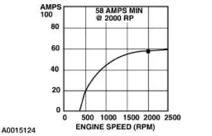
6. With the engine running at 2,000 rpm, adjust the tester load bank to determine the output of the generator. Generator output should be at least 58 amps.
Generator On-Vehicle Tests-No Load Test
1. Switch the battery tester to the voltmeter function.
2. Connect the voltmeter positive lead to the generator B+ output terminal, circuit 38 (BK/OG) and the negative lead to ground.
3. Turn all electrical accessories off.
4. With the engine running at 2,000 rpm, check the generator output voltage. The voltage should be between 13.0 and 15.0 volts. If not, refer to the Symptom Chart.
 Pinpoint Tests
CAUTION: Do not make jumper connections except as directed.
Incorrect connections
may damage the voltage regulator test terminals, fuses, or fuse links.
CAUTION: Do not allow any metal object ...
 Battery, Mounting and Cables
General Specifications
Torque Specifications
...
Other materials:
Reactivation Procedure
1. WARNING: The restraint system diagnostic tool must be removed and
the air bag
modules reconnected when the system is reactivated to avoid non-deployment in a
collision, resulting in possible personal injury.
WARNING: The restraint system diagnostic tool i ...
Pulley - CIII Pump
Special Tool(s)
Pump Pulley Replacer
211-185 (T91P-3A733-A)
Pump Pulley Remover
211-016 (T69L-10300-B)
Removal
1. Remove the drive belt.
2. Raise and support the vehicle.
3. Using the special tool, remove the pulley.
Inspect the p ...
Bypass Tube - 3.8L
Material
Item
Specification
Motorcraft Premium Gold
Engine Coolant
VC-7-A (in Oregon VC-7-B)
(yellow color)
WSS-M97B51-
A1
Removal and Installation
1. Drain the engine coolant. For additional information, refer to Cooling
System Dra ...
