Ford Mustang (1999-2004) Service Manual: Component Tests
Drive Belt Noise/Flutter
Drive belt chirp occurs due to pulley misalignment or excessive pulley runout. It can be the result of a damaged pulley or an incorrectly aligned pulley.
To correct, determine the area where the noise comes from. Check each of the pulleys in that area with a straightedge to the crankshaft pulley, looking for accessory pulleys out of position in the fore/aft direction or at an angle to the straightedge.
Drive belt squeal is an intermittent noise that occurs when the drive belt slips on a pulley during certain conditions, such as: engine start up, rapid engine acceleration, or A/C clutch engagement.
Drive belt squeal can occur:
- if any of the accessories are damaged, have a worn or damaged bearing,
internal torsional
resistance above normal. All accessories should be rotatable by hand in the
unloaded condition.
If not, inspect the accessory.
- if fluid gets on the drive belt. This includes power steering fluid, engine coolant, engine oil or air conditioning system lubricant. If fluid does get on the drive belt during service, clean the drive belt with soap and water and thoroughly rinse with clean water.
- NOTE: The drive belt tensioner arm should rotate freely without
binding.
if the drive belt is too long. A drive belt that is too long will allow the drive belt tensioner arm to go all the way to the arm travel stop under certain load conditions, which will release tension to the drive belt. If the drive belt tensioner indicator is outside the installation wear range window, install a new drive belt.
- if the drive belt tensioner is worn or damaged.
Belt Tension
NOTE: Drive belt tension is not adjustable.
The drive belt tensioner automatically adjusts drive belt tension.
Belt Tensioner, Automatic
Check the automatic drive belt tensioner:
1. With the engine off, check for correct drive belt routing; refer to Accessory Drive. Repair as necessary.
2. Rotate the drive belt tensioner and check for a binding or frozen condition. Install new components as necessary.
Drive Belt Misalignment
CAUTION: Incorrect drive belt installation will cause excessive drive belt wear and may cause the drive belt to come off the drive pulleys.
Non-standard drive belts may track differently or incorrectly. If a drive belt tracks incorrectly, install it with an original equipment drive belt to avoid performance failure or loss of drive belt.
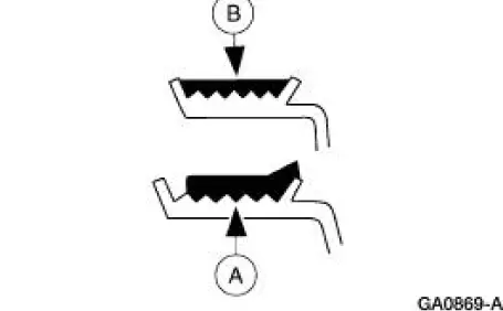
With the engine running, check drive belt tracking. If the (A) edge of the drive belt rides beyond the edge of the pulleys, noise and premature wear may occur. Make sure the (B) drive belt rides correctly on the pulley. If a drive belt tracking condition exists, proceed with the following:
- Visually check the drive belt tensioner for damage, especially the
mounting pad surface. If the
drive belt tensioner is not installed correctly, the mounting surface pad
will be out of position.
This will result in chirp and squeal noises.
- With the engine running, visually observe the grooves in the pulleys (not the pulley flanges or the pulley forward faces) for excessive wobble. Install new components as necessary.
- Check all accessories, mounting brackets and the drive belt tensioner for any interference that would prevent the component from mounting correctly. Correct any interference condition and recheck the drive belt tracking.
- Tighten all accessories, mounting brackets, and drive belt tensioner retaining hardware to specification. Recheck the drive belt tracking.
 Inspection and Verification
1. Verify customer concern by running the engine.
2. Inspect the drive belt for chunking, fraying and wear.
3. Check the drive belt for correct routing.
Drive Belt Cracking/Chunking/Wear
V Ribbed Se ...
 Accessory Drive Belt - 3.8L
Removal and Installation
1. Rotate the drive belt tensioner counterclockwise and remove the drive
belt.
2. NOTE: Make sure the drive belt is correctly installed on each
pulley.
To install, reverse ...
Other materials:
Exterior mirrors
Power Exterior Mirrors
WARNING: Do not adjust the mirror while your vehicle is in
motion.
A. Left mirror
B. Off
C. Right mirror
To adjust your mirrors:
1. Select the mirror you want to adjust.
2. Move the control in the direction you want to tilt the mirror.
...
Torque Converter (Description and Operation)
The torque converter transmits and multiplies torque. The torque
converter is a four-element device:
impeller assembly
turbine assembly
reactor assembly
clutch and damper assembly
The standard torque converter components operate as follo ...
Windshield wipers
Note: Fully defrost the windshield before switching on the windshield
wipers.
Note: Make sure you switch off the windshield wipers before entering a
car wash.
Note: Clean the windshield and wiper blades if they begin to leave
streaks or smears. If that does ...
