Ford Mustang (1999-2004) Service Manual: Disassembly
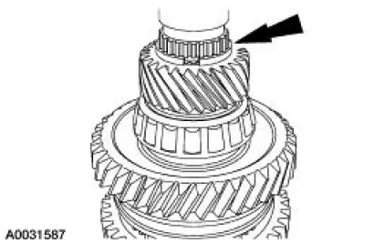
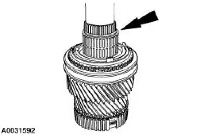
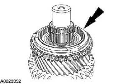
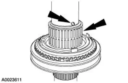
1. Remove the retaining ring above fifth gear.
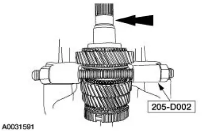
2. CAUTION: Hand tighten the special tool to prevent gear damage.
CAUTION: Support the output shaft while using the press to prevent damage to the shaft or gears.
Using the special tool, press fifth gear, the spacer, the output shaft bearing and reverse gear from the output shaft.
- Discard the output shaft bearing.

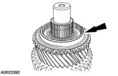
3. Remove reverse gear needle bearing.
- Inspect the needle bearing for wear or damage. Install a new needle bearing as necessary.
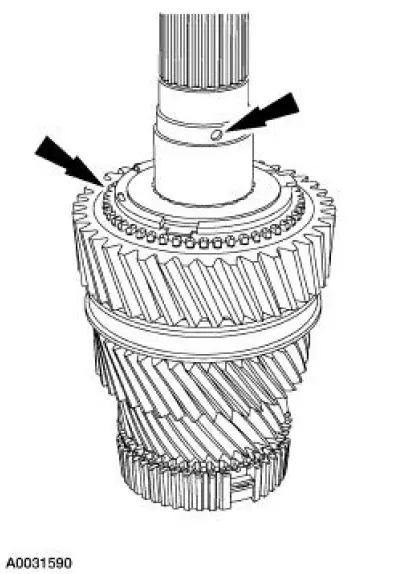
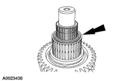
4. Remove the check ball and the blocking ring.
- Inspect the blocking ring for wear or damage. Install new blocking rings as necessary.
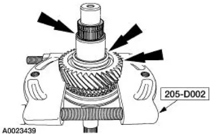
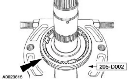
5. NOTE: Install the special tool with the flat side facing first gear.
Using the special tools, press the bearing spacer, the reverse gear synchronizer cone and first gear from the output shaft.
6. Remove the first gear needle bearing.
- Inspect the needle bearing for wear or damage. Install a new needle bearing as necessary.
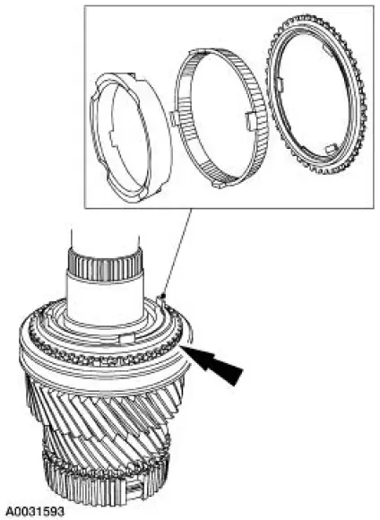
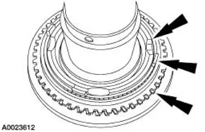
7. Remove the first gear synchronizer inner cone, the first gear synchronizer outer cone and the first gear synchronizer blocking ring.
- Inspect all components for wear or damage. Install new components as necessary.
8. NOTE: Reposition the output shaft on the press with the input shaft end facing upward.
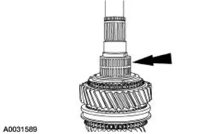
- Remove and discard the retaining ring.
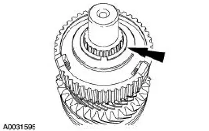
9. Remove the third/fourth synchronizer hub.
10. Remove the third/fourth blocking ring.
11. Remove the third gear.
- Inspect the gear for wear or damage. Install a new gear as necessary.
12. Remove the third gear needle bearing.
- Inspect the needle bearing for wear or damage. Install a new needle bearing as necessary.
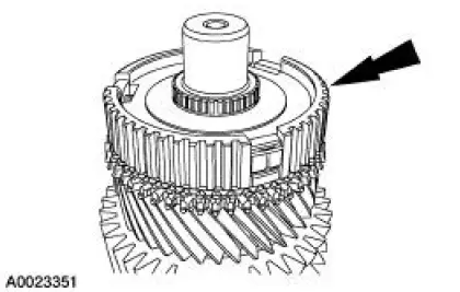
13. NOTE: Install the special tool behind second gear with the flat side of the tool facing second gear.
Using the special tool, remove the spacer, second gear thrust washer and second gear.
- Inspect the gear for wear or damage. Install a new gear as necessary.
14. Remove the check ball and second gear needle bearing.
- Inspect the needle bearing for wear or damage. Install a new needle bearing as necessary.
15. Remove the second gear synchronizer inner cone, second gear synchronizer outer cone and the second gear synchronizer blocking ring.
- Inspect all components for wear or damage. Install new components as necessary.
16. Remove the snap ring, then using the special tool, press off the first/second gear synchronizer.
 Output Shaft
Special Tool(s)
Remover, Drive Pinion Bearing
Cone
205-D002 (D79L-4621-A) or
equivalent
Installer, Drive Pinion Bearing
Cone
205-011 (T57L-4621-B)
...
 Assembly
1. Carry out the following before reassembling:
Inspect the gears for broken or cracked teeth. Check for unusual wear
patterns.
Inspect the thrust washers for face wear, cracks, scoring and for s ...
Other materials:
Camshaft Lobe Lift
Special Tool(s)
Dial Indicator Gauge with
Holding Fixture
100-002 (TOOL-4201-C) or
equivalent
1. Use a Dial Indicator Gauge with Holding Fixture to measure camshaft
intake/exhaust lobe lift.
Rotate the camshaft and subtract the lowest ...
Headlamp exit delay
You can set the delay time to keep the headlamps on for up to three
minutes after the ignition is turned off.
Follow the steps below to change the delay time (Steps 1 through 6
must be done within 10 seconds):
1. Turn the ignition off.
2. Turn the lighting co ...
Electronic Vibration Analyzer (EVA)
The EVA is a hand-held electronic diagnostic tool which will assist in
locating the source of
unacceptable vibrations. The vibration sensor can be remotely mounted anywhere
in the vehicle for
testing purposes. The unit displays the three most common vibratio ...
