Ford Mustang (1999-2004) Service Manual: Connecting Rod - Bearing Journal Clearance
Special Tool(s)
|
|
Plastigage 303-D031 (D81L-6002-B) or equivalent |
NOTE: The crankshaft connecting rod journals must be within specifications to check the connecting rod bearing journal clearance.
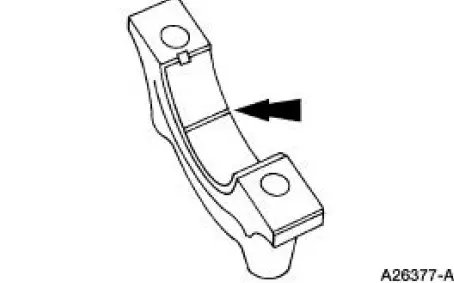
1. Remove the connecting rod bearing cap.
2. Position a piece of Plastigage across the bearing surface.
3. NOTE: Do not turn the crankshaft during this step.
Install and tighten to specifications, then remove the connecting rod bearing cap.
4. Measure the Plastigage to get the connecting rod bearing journal clearance. The Plastigage should be smooth and flat. A changing width indicates a tapered or damaged connecting rod or connecting rod bearing.
- Refer to the appropriate section in Group for the procedure.
- If out of specification, install new components as necessary. Refer to the appropriate section in Group for the procedure.

 Connecting Rod - Twist
1. Measure the connecting rod twist on a suitable alignment fixture.
Follow the instructions of the
fixture manufacturer. Verify the measurement is within specification.
Refer to the appropriat ...
 Connecting Rod - Side Clearance
1. Measure the clearance between the connecting rod and the crankshaft.
Verify the measurement
is within specification.
Refer to the appropriate section in Group for the procedure.
If out of ...
Other materials:
Tire Wear Chart
Wheel and tire NVH concerns are directly related to vehicle speed and are not
generally affected by
acceleration, coasting or decelerating. Also, out-of-balance wheel and tires can
vibrate at more than
one speed. A vibration that is affected by the engine ...
Installation
1. Install the bearing, snap ring, hub and dust shield. For additional
information, refer to Wheel
Hub-Cobra in this section.
2. Install the knuckle.
1. Position the knuckle on the lower suspension arm and bushing.
2. Install a new bolt and a new nut. Do ...
Generator and Regulator
General Specifications
Torque Specifications
Generator
The charging system consists of the:
generator (GEN)
internal voltage regulator
The generator has an internal voltage regulator that is not installed
separately. The generator and
v ...
