Ford Mustang (1999-2004) Service Manual: Daytime Running Lamps (DRL) (Diagnosis and Testing)
Refer to Wiring Diagrams Cell 97 , Daytime Running Lamps for schematic and connector information.
Special Tool(s)
 |
73III Automotive Meter or equivalent 105-R0057 |
Principles of Operation
Daytime Running Lamps (DRL)
The daytime running lamps (DRL) system operates the low beam headlamps at a reduced intensity.
The DRL module (15A270) supplies pulse width modulated (PWM) voltage, approximately 75%-92% of battery voltage, to the low beam headlamps when the following conditions are met:
- The parking brake control is released.
- The high beam headlamps are disabled.
- The ignition switch (11572) is in the RUN position.
The DRL module remains enabled when the low beam headlamps are turned on.
Inspection and Verification
1. Verify the customer concern by operating the system.
2. Visually inspect for obvious signs of mechanical and electrical damage.
Visual Inspection Chart
| Mechanical | Electrical |
|
|
3. Verify the headlamps are operating correctly. Correct any concerns before proceeding to the next step. For additional information, refer to Section.
4. Verify the parking brake control is fully released.
5. If an obvious cause for an observed or reported concern is found, correct the cause (if possible) before proceeding to the next step.
6. If the concern is not visually evident, verify the symptom and refer to the Symptom Chart.
Symptom Chart
| Condition | Possible Sources | Action |
|
|
|
|
|
|
|
|
|
|
|
|
|
|
|
Pinpoint Tests
PINPOINT TEST A: THE DAYTIME RUNNING LAMPS ARE INOPERATIVE
| Test Step | Result / Action to Take |
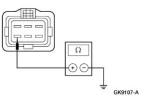
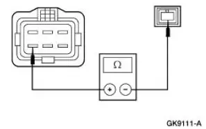
| A1 CHECK THE PARKING BRAKE SWITCH SIGNAL CIRCUIT TO THE DRL MODULE FOR SHORT TO GROUND | Yes GO to A3 . No GO to A2 . |
NOTE: Verify the parking brake control is fully released for this step.
|
|
| A2 CHECK THE PARKING BRAKE SWITCH | Yes INSTALL a new parking brake signal switch and bracket. TEST the system for normal operation. No REPAIR the circuit. TEST the system for normal operation |
|
|
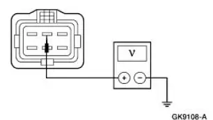
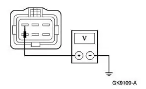
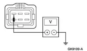
| A3 CHECK VOLTAGE TO THE DRL MODULE | Yes GO to A4 . No REPAIR the circuit. TEST the system for normal operation. |
|
|
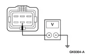
| A4 CHECK IGNITION SENSE INPUT | Yes GO to A5 . No REPAIR the circuit. TEST the system for normal operation. |
|
|
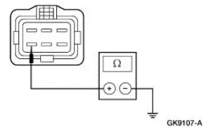
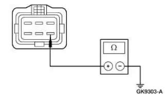
| A5 CHECK THE DRL MODULE GROUND - CIRCUIT 1205 (BK) | Yes GO to A6 . No REPAIR the circuit. TEST the system for normal operation |
|
|
| A6 CHECK THE HIGH BEAM DISABLE INPUT CIRCUIT FOR SHORT TO BATTERY - CIRCUIT 12 (LG/BK) | Yes REPAIR the circuit. TEST the system for normal operation. No INSTALL a new DRL module. REFER to Module-Daytime Running Lamps (DRL) . TEST the system for normal operation. |
|
PINPOINT TEST B: THE DAYTIME RUNNING LAMPS ARE ON WITH THE PARKING BRAKE SET
| Test Step | Result / Action to Take |
| B1 CHECK THE PARKING BRAKE SWITCH | Yes INSTALL a new parking brake signal switch and bracket. TEST the system for normal operation. No GO to B2 . |
|
|
| B2 CHECK THE PARKING BRAKE SWITCH SIGNAL CIRCUIT | Yes INSTALL a new DRL module. REFER to Module-Daytime Running Lamps (DRL) . TEST the system for normal operation. No REPAIR the circuit. TEST the system for normal operation. |
|
PINPOINT TEST C: THE DAYTIME RUNNING LAMPS ARE ON WITH THE IGNITION SWITCH OFF
| Test Step | Result / Action to Take |
| C1 CHECK THE IGNITION SWITCH INPUT TO THE DRL MODULE FOR VOLTAGE | Yes GO to C2 . No INSTALL a new DRL module. REFER to Module-Daytime Running Lamps (DRL) . TEST the system for normal operation. |
|
|
| C2 CHECK THE IGNITION SWITCH | Yes REPAIR Circuit 298 (VT/OG) for short to battery. TEST the system for normal operation. No INSTALL a new ignition switch. REFER to Section. TEST the system for normal operation. |
|
PINPOINT TEST D: THE LOW BEAM HEADLAMPS ARE ON AT FULL INTENSITY IN DRL MODE
| Test Step | Result / Action to Take |
| D1 CHECK THE LOW BEAM HEADLAMPS INPUT | Yes REFER to Section. No INSTALL a new DRL module. REFER to Module- Daytime Running Lamps (DRL) . TEST the system for normal operation. |
|
 Daytime Running Lamps
Torque Specifications
Daytime Running Lamps (DRL)
The daytime running lamp (DRL) system consists of a daytime running lamp
module and bracket
assembly (15A270). The module is located on the front ...
 Module - Daytime Running Lamps (DRL)
Removal
1. CAUTION: Electronic modules are sensitive to static electrical
charges. If exposed
to these charges, damage can result.
Disconnect the battery ground cable.
2. Remove the daytime runn ...
Other materials:
Transmission (Installation)
Material
Item
Specification
DEXRON III (ATF)
Transmission Fluid
XT-2-QDX or equivalent
DEXRON III
Pipe Sealant with Teflon
D8AZ-19554-A or equivalent
WSK-M2G350-
A2
Premium Long Life Grease
XG-1-C, K or T or equivalent
...
Interior Lighting (Diagnosis and Testing)
Refer to Wiring Diagrams Cell 111 , Remote Control Alarm and Lock System
for schematic and
connector information.
Refer to Wiring Diagrams Cell 59 , Generic Electronic Module for schematic
and connector
information.
Refer to Wiring Diagrams Cell 89 , ...
Pinpoint Test H: LFC 32/DTC B1932 - Driver Air Bag Circuit Resistance High
Normal Operation
The restraints control module (RCM) monitors the resistance for the
driver air bag ignitor by measuring
the resistance between pins 3 and 4. If the RCM detects high resistance
between these pins, it will
store a diagnostic trouble code ...
