Ford Mustang (1999-2004) Service Manual: Installation
1. NOTE: The LH side is shown, and the RH is similar.
Install the supply manifold and tighten the four bolts.
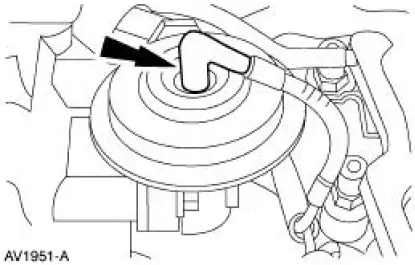
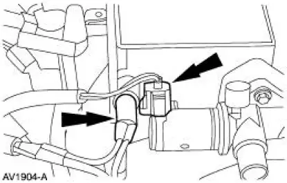
2. Connect the EGR vacuum line.
3. Install the EGR to exhaust manifold tube. For additional information, refer to Section.
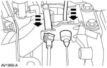
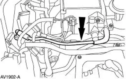
4. NOTE: The engine is removed for clarity.
Position the EVR bracket and tighten the bolts.
5. Connect the EVR solenoid vacuum lines.
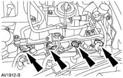
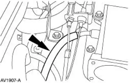
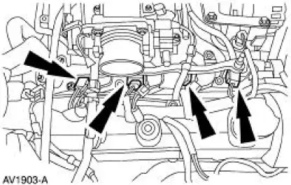
6. Connect the LH fuel injector electrical connectors.
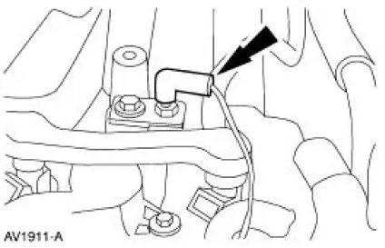
7. Connect the ground wire.
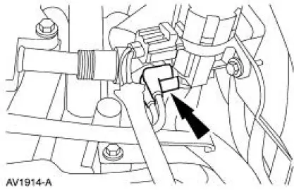
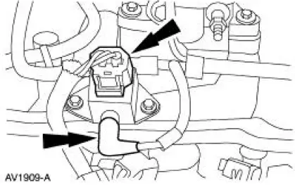
8. Connect the fuel pressure sensor electrical connector and the vacuum hose.
9. NOTE: Make sure the locking clips are fully engaged into the bracket.
Reposition the accelerator cable and the speed control cable (if equipped) and install the cables into the bracket.
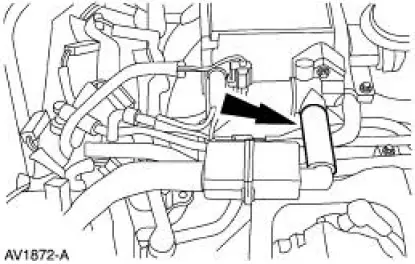
10. Connect the hose.
11. Connect the IAC electrical connector and install the main chassis vacuum hose.
12. Connect the four RH fuel injector electrical connectors.
13. Connect the PCV hose.
14. Position the IAC hose and connect the hose.
15. Install the throttle body.
16. Connect the fuel line.
17. Connect the air cleaner outlet tube.
18. Connect the battery ground cable.
 Removal
WARNING: Do not smoke or carry lighted tobacco or open flame of any
type when
working on or near any fuel related components. Highly flammable mixtures are
always present
and may be ignited. Failure ...
 Fuel Charging and Controls - Cobra 4.6L (4V)
General Specifications
Torque Specifications
...
Other materials:
Accelerator Cable Bracket - Supercharged Engine
Removal and Installation
1. Disconnect the accelerator cable and speed control cable.
2. Depress the tabs and disconnect the accelerator cable and speed control
cable from the
accelerator cable bracket
3. Remove the bolts and the accelerator cable bracket ...
Bushing - Stabilizer Bar
Removal
CAUTION: Suspension fasteners are critical parts because they affect
performance of vital
components and systems and their failure can result in major service expense. A
new part with
the same part number or an equivalent part must be installed, if i ...
Assembly
1. Install the new O-ring.
2. Assemble the gear shifter forks.
1. Install the gear shift plate into the gear shifter fork.
2. Install the gear shift fork inserts.
3. NOTE: Position the narrow side of the C-shaped gear selector
interlock sleeve in ...
