Ford Mustang (1999-2004) Service Manual: Disassembly
Initial disassembly
1. Remove the differential housing cover (4033) and drain the lubricant into a suitable container.
2. Wipe the lubricant from the internal working parts and inspect the parts for wear and damage.
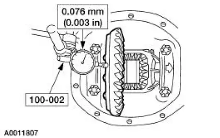
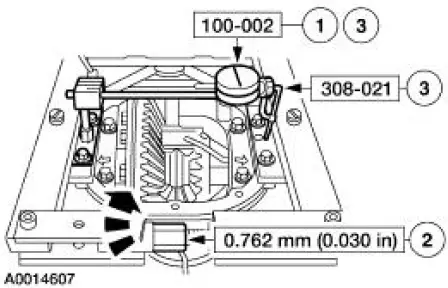
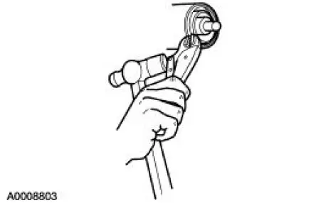
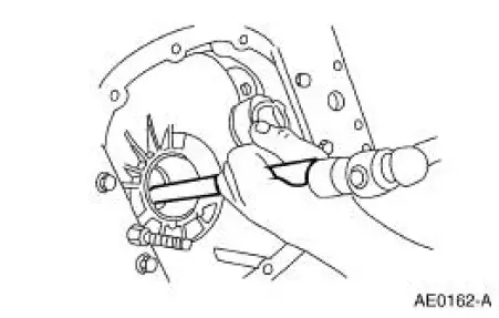
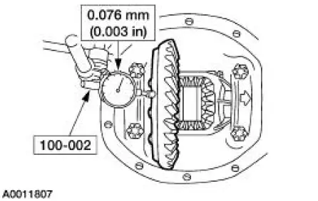
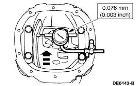
3. Using the special tool, measure and note the differential ring gear backface runout.
- Remove the special tool.
4. CAUTION: Do not damage the aluminum differential housing (4010) while carrying out these procedures.
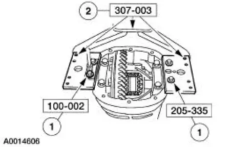
Using the special tools, mount the differential housing to a work bench.
1. Attach the special tools to the differential housing with four bolts that retain the differential housing cover to the differential housing.
2. Attach the special tools together with two 3/8 inch x 1-1/2 inch bolts.
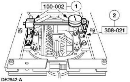
5. Install the special tool by placing the spreader pins in the hole in the Housing Spreader Adapters.
6. Assemble the special tool.
1. Install the special tool.
2. Attach the special tool and position the tip in the Housing Spreader Adapter hole.
7. CAUTION: Overspreading can damage the differential housing.
NOTE: Tighten and loosen the Differential Carrier Spreader screw to normalize the Housing Spreader Adapters prior to taking the final Dial Indicator reading.
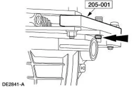
Spread the differential housing to the specification.
1. Adjust the special tool to zero.
2. Tighten the screw until the differential housing is spread to the specification.
3. Remove the special tools.
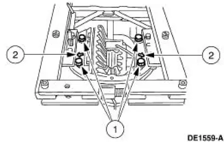
8. CAUTION: Mark the position and location of the differential bearing caps as the arrows may not be visible. Always install the differential bearing caps in their identical location and position.
Remove the differential bearing caps.
1. Remove the bolts.
2. Remove the differential bearing caps.
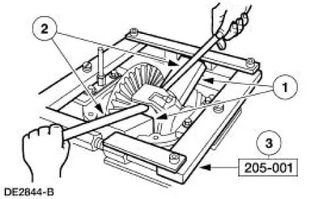
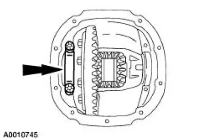
9. CAUTION: Use wood blocks to avoid damaging the differential housing.
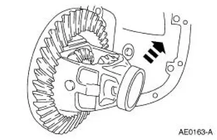
Remove the differential assembly.
1. Position wood blocks at the top and bottom of the differential case (4204).
2. Pry the differential assembly and the differential bearing shims (4067) out of the differential housing.
3. Remove the special tool.
10. CAUTION: Record the torque necessary to maintain rotation of the drive pinion gear through several revolutions prior to removing the rear axle pinion flange (4851).
Remove the rear axle pinion flange. For additional information, refer to Drive Pinion Flange in this section.
11. Using a screwdriver, force the rear axle drive pinion seal metal flange up and strike it with a hammer.
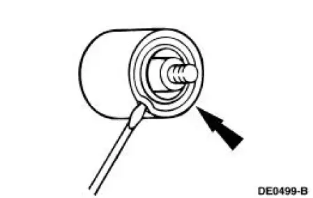
12. Using gripping pliers and a hammer, remove the rear axle drive pinion seal (4676).
13. Remove the rear axle drive pinion shaft oil slinger (4670).
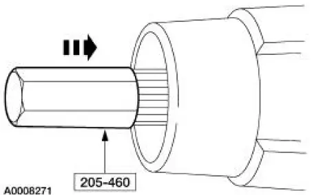
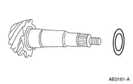
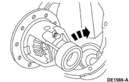
14. Using the special tool and a soft-faced hammer, drive the drive pinion gear out of the front pinion bearing (4621) and remove it through the rear of the differential housing.
15. Remove and discard the differential drive pinion collapsible spacer (4662).
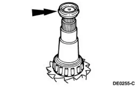
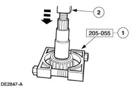
16. Using the special tool and a suitable press, remove the pinion bearing (4630).
1. Position the special tool under the pinion bearing.
2. Using a press, remove the pinion bearing.
17. NOTE: Using a micrometer, measure the drive pinion bearing adjustment shim thickness. Use this measurement as a reference to compare to the shim gauge reading taken prior to installing the pinion bearing.
Remove the drive pinion bearing adjustment shim (4663).
18. Using a brass drift and a hammer, remove any damaged differential drive pinion bearing cup (4616) (4628) from the differential housing. Tap alternately on each side of the cup to prevent it from cocking in the bore.
19. If the differential ring gear backface runout measurement, taken at the beginning of this procedure, did not exceed the specification, proceed to Final disassembly in this procedure. If the differential ring gear backface runout measurement, taken at the beginning of this procedure, exceeded the specification, the cause may be a warped differential ring gear, a damaged differential case, or loss of differential bearing preload. Proceed to Excessive differential ring gear backface runout in this procedure to verify the cause of the excessive runout.
Excessive differential ring gear backface runout
20. Place the differential assembly with the differential bearings (4221) and the differential bearing cups (4222) in the differential housing.
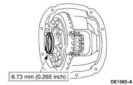
21. Install a differential bearing shim of the thickness shown on the LH side of the differential case.
22. Install the LH differential bearing cap finger-tight.
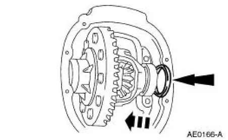
23. NOTE: Apply pressure toward the left side to fully seat the differential bearing cup.
Install progressively larger differential bearing shims on the RH side until the largest differential bearing shim selected can be assembled with a slight drag feel.
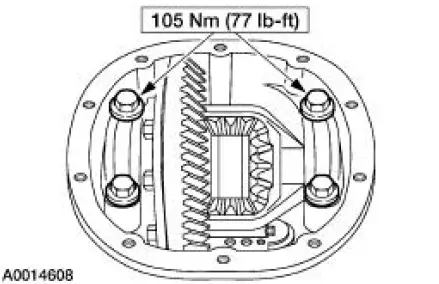
24. Install the RH differential bearing cap.
- Tighten both bearing caps to specification.
25. Rotate the differential assembly to make sure it turns freely.
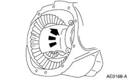
26. Using the special tool, measure and record the differential ring gear backface runout.
- If the runout does not exceed the specification, the cause of the original excessive runout was due to a loss of differential bearing preload. Proceed to Final disassembly in this procedure.
- If the runout exceeds the specification, proceed as follows.
- Remove the special tool.
27. Remove the differential assembly.
28. Remove the bolts.
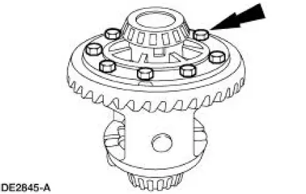
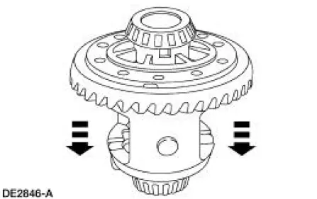
29. CAUTION: Do not damage the bolt hole threads.
Insert a punch in the bolt holes and drive off the differential ring gear.
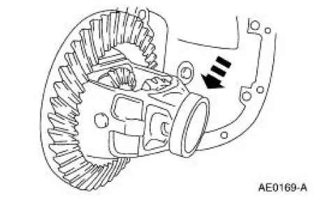
30. Install the differential case. Rotate the differential case to seat the differential bearings.
31. Using the special tool, measure the differential case flange runout.
- If the runout does not exceed the specification, the cause of the original excessive runout is the differential ring gear. Remove the differential case. Discard the differential ring gear and the drive pinion gear. Proceed to Final disassembly in this procedure.
- If the runout exceeds the specification, the differential ring gear is
true and the concern is
due to either differential case/differential bearing damage. Remove the
differential case.
Discard the differential bearings/differential case. Proceed to Final disassembly in this procedure.
- Remove the special tool.
 Axle
Axle
Special Tool(s)
2-Jaw Puller
205-D072 (D97L-4221-A) or
equivalent
Adapter for 205-S127
205-105 (T76P-4020-A3)
Bearing Preload Tool
205-395 (T93P-4220-A)
Plat ...
 Final disassembly
32. If not done previously, remove the bolts.
33. CAUTION: Do not damage the bolt hole threads.
If not done previously, insert a punch in the bolt holes and drive off the
differential ring gear.
...
Other materials:
Oil Filter Adapter
Material
Item
Specification
Super Premium SAE 5W-20
Motor Oil
XO-5W20 QSP or equivalent
WSS-M2C153-
H
Premium Engine Coolant
VC-4A (In Canada CXC-10; In
Oregon VC-5) or equivalent
ESE-M97B44-
A
Removal and Installation
1. ...
Suction Accumulator
NOTE: Installation of a new suction accumulator is not required when
repairing the air conditioning
system except when there is physical evidence of contamination from a failed A/C
compressor or
damage to the suction accumulator.
In addition to th ...
Transmission Filler Tube
Removal
1. Remove the bolt.
2. Remove the fluid filler tube.
Installation
1. To install, reverse the removal procedure.
...
