
Ford Mustang (1999-2004) Service Manual: Component Test
Windshield Wiper Motor
CAUTION: Do not handle the wiper motor abusively when diagnosing the wiper operations. Failure to follow this caution may result in damage to the motor magnets and will make the wiper motor inoperative. Rough handling of new replacement wiper motors may also damage the motor magnets.
Use Alternator, Regulator, Battery and Starter Tester (ARBST) to test the wiper motor on the vehicle.
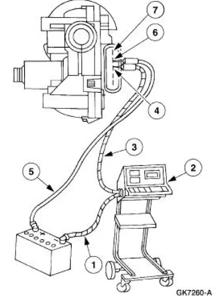
To test the wiper motor, disconnect the windshield wiper mounting arm and pivot shaft from the windshield wiper motor; refer to Pivot Arm .
Disconnect the wiper motor. Connect the (1) green lead from (2) (ARBST) to the battery negative (-) post. Connect the (3) red lead from ARBST to the wiper motor (4) common brush terminal (terminal 3).
Test the low speed mode by connecting a (5) cable from the battery positive (+) post to the (6) low speed brush terminal (terminal 4) and measure the current draw. If the current draw is greater than 3.5 amperes, install a new windshield wiper motor.
Test the high speed mode by connecting a cable from the battery positive (+) post to the (7) high speed brush terminal (terminal 5) and measure the current draw. If the current draw is greater than 5.5 amperes, install a new wiper motor.
 Pinpoint Tests
CAUTION: Before removing and installing the GEM or its connectors,
disconnect the
battery. Failure to follow this caution will result in the GEM storing many
erroneous DTCs and it
may exhibit errati ...
 Wiper Blade and Pivot Arm Adjustment
1. Cycle and park the windshield wipers.
2. Verify that the distance between the center of the RH windshield
wiper blade and the top edge
of the cowl top vent panel is within specification.
...
Other materials:
Ignition Coil
Material
Item
Specification
Silicone Brake Caliper Grease
and Dielectric Compound
D7AZ-19A331-A or equivalent
ESE-M1C171-
A
Removal and Installation
1. Disconnect the battery ground cable (14301). For additional
information, refer to ...
Ignition Lock Cylinder - Functional
Removal and Installation
1. Disconnect the battery ground cable. For additional information,
refer to Section.
2. Remove the ignition switch lock cylinder (11582).
1. Insert the ignition key and turn to the RUN position.
2. Using a 1/8-inch d ...
Pump - CII
Special Tool(s)
Teflon Seal Replacer Set
211D027 (D90P-3517-A) or
equivalent
Removal and Installation
1. Disconnect the power steering hose. Remove and discard the seal ring.
2. Disconnect the power steering hose.
3. Remove the pulley.
...
