Ford Mustang (1999-2004) Service Manual: Final disassembly
32. If not done previously, remove the bolts.
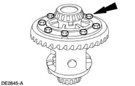
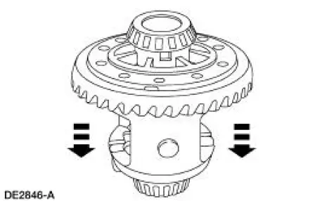
33. CAUTION: Do not damage the bolt hole threads.
If not done previously, insert a punch in the bolt holes and drive off the differential ring gear.
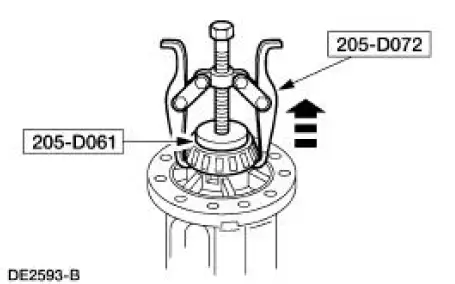
34. Using the special tools, remove the differential bearing.
- Repeat for the other side.
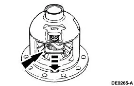
35. Remove the bolt and remove the differential pinion shaft (4211).
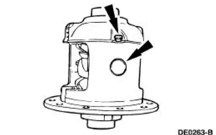
36. WARNING: The differential clutch spring (4214) is under tension. Remove the spring carefully. Failure to follow these instructions may result in personal injury.
Remove the differential clutch spring.
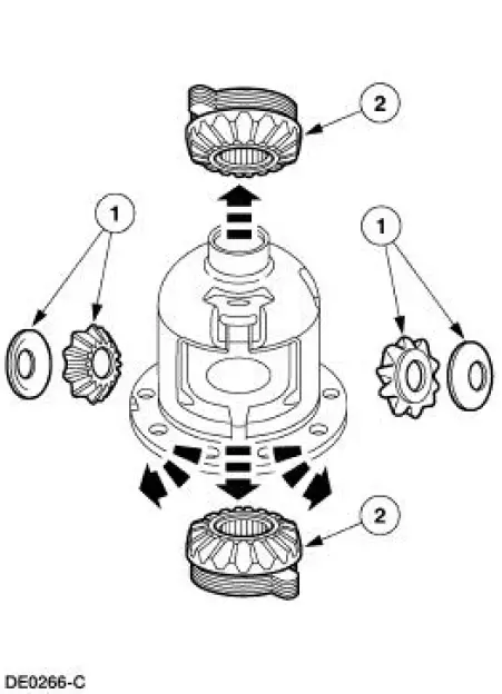
37. Remove the differential gears.
1. Remove the two differential pinion gears (4215) and pinion thrust washers (4230).
2. Remove the two differential side gears (4236) with the clutch packs (4947) and the shims and tag them "left" and "right."
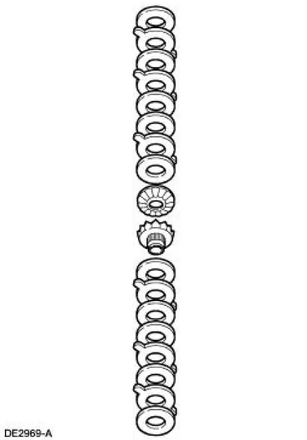
38. CAUTION: Keep the differential clutch packs in order. Do not mix them. Always reassemble them in the same sequence.
Remove the differential clutch packs and shims from the differential side gears.
- Clean and inspect the remaining differential components for wear and damage. Install new parts as necessary.
39. CAUTION: Do not use acids or solvents when cleaning the differential clutch packs.
Wipe the components only with a clean, lint-free cloth.
Clean and inspect the differential clutch packs for wear and damage. Install new parts as necessary.
 Disassembly
Initial disassembly
1. Remove the differential housing cover (4033) and drain the lubricant into
a suitable container.
2. Wipe the lubricant from the internal working parts and inspect the parts for ...
 Assembly
Initial assembly
1. Coat the new differential drive pinion bearing cup(s) with lubricant.
Use SAE 75W-140 High Performance Rear Axle Lubricant F1TZ-19580-B or
equivalent
meeting Ford specificatio ...
Other materials:
Supply Manifold
Removal and Installation
WARNING: Do not smoke or carry lighted tobacco or open flame of any
type when
working on or near any fuel related components. Highly flammable mixtures are
always present
and may ignite. Failure to follow these instructions may resul ...
Installation
1. Install the upper intake manifold gasket.
2. Install the intake manifold and bolts in the sequence shown.
3. Install the PCV valve-to-intake manifold tube.
4. Connect the vacuum hoses and the electrical connector to the EGR vacuum
regulator soleno ...
Installation
1. NOTE: A new torque converter drain plug must be used.
Install the torque converter drain plug.
2. Install the torque converter housing plug.
3. CAUTION: If installing a new filter, and the seal remains in the
main control bore,
carefully use a small ...
