Ford Mustang (1999-2004) Service Manual: Disassembly
NOTE: The steering gear is serviceable as either a long or short rack assembly. This procedure covers the removal and installation of the components not supplied with a short rack assembly. On short rack assembly only the front wheel spindle tie-rods and front suspension steering ball stud dust seals are serviced separately.
All steering gears
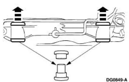
1. Remove the steering gear mounting bracket housing insulators.
- Discard worn or damaged steering gear mounting bracket housing insulators.
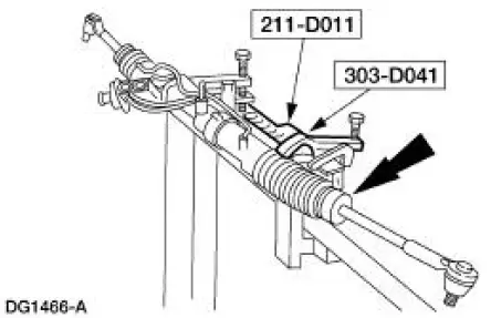
2. Install the steering gear into the special tools.
3. Clean the exterior of the steering gear with solvent. If necessary, drain any excess power steering fluid.
4. Inspect the steering gear housing for cracks and other damage. If necessary, install a new steering gear.
5. Verify the power steering gear input shaft bearing rotates freely. If necessary, install a new steering gear.
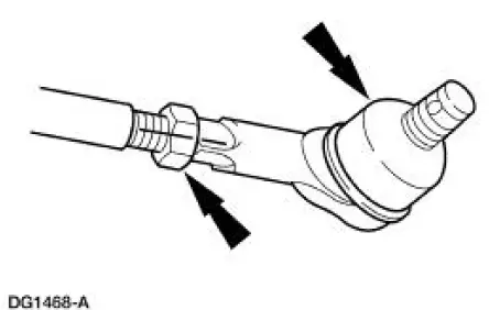
6. Place an alignment mark on the tie-rod ends, nuts and front wheel spindle tie-rods. Remove the tie-rod ends and nuts.
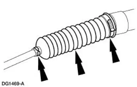
7. CAUTION: Use care not to damage the front suspension steering ball stud dust seals. If the front suspension steering ball stud dust seals are damaged, this will allow contamination into the steering gear and cause leakage.
Remove the clamps and the two front suspension steering ball stud dust seals.
- Discard any clamps that are damaged or excessively corroded.
- Discard any front suspension steering ball stud dust seals that are damaged.
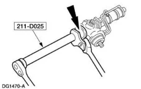
8. CAUTION: Place the steering gear at the center position. Use a crowfoot on the flat of the rack gear to resist rotation and prevent damage to the steering gear during removal and installation of the front wheel spindle tie-rods.
Place the steering gear at the center position. Install a crowfoot on the flat of the steering gear.
Using the special tool remove the front wheel spindle tie-rods.
Steering gears equipped with travel restrictors
9. NOTE: Some steering gears may contain one or two rack travel restrictors on each side of the steering gear. The restrictors are split washers and can be removed if necessary.
Remove the travel restrictors.
- Discard any travel restrictors that are heavily worn.
All steering gears
10. Remove the steering gear from the special tools.
 Gear (Disassembly and Assembly)
Special Tool(s)
Head Mounting Fixture
303-D041 (D83L-500-B1) or
Equivalent
Inner Tie Rod Socket Tool
211-D025 (D90P-3290-A) or
Equivalent
Steering Gear Holding Fixtur ...
 Assembly
All steering gears
1. Install the steering gear in the special tools.
Steering gears equipped with travel restrictors
2. Install the travel restrictors.
Install new travel restrictors as necessary.
...
Other materials:
Inspection and Verification
1. Verify the customer concern by operating the engine to duplicate the
condition.
2. Visually inspect for obvious signs of mechanical damage. Refer to the
following chart.
Visual Inspection Chart
Mechanical
Engine coolant leaks
...
Electronic Vibration Analyzer (EVA)
The EVA is a hand-held electronic diagnostic tool which will assist in
locating the source of
unacceptable vibrations. The vibration sensor can be remotely mounted anywhere
in the vehicle for
testing purposes. The unit displays the three most common vibratio ...
Valve Cover RH
Material
Item
Specification
Metal Surface Cleaner
F4AZ-19A536-RA or equivalent
WSE-M5B392-
A
Silicone Gasket and Sealant
F7AZ-19554-EA or equivalent
WSE-M4G323-
A4
PAG Refrigerant Compressor
Oil
F7AZ-19589-DA (Motorcraf ...
