Ford Mustang (1999-2004) Service Manual: Torque Converter Turbine to Pump Stator Interference Check
1. NOTE: Front pump support may remain in front pump support and gear during this test.
Position the torque converter with the pump drive up.
2. Install the front pump support to engage the mating splines of the front pump support shaft on the torque converter.
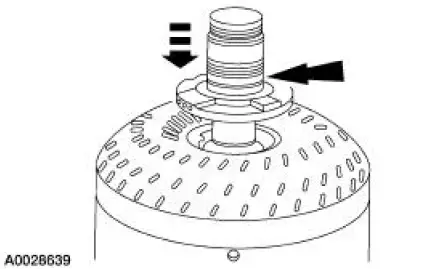
3. Install the forward clutch cylinder and shaft, engaging the splines with the rear clutch hub.
4. Check for stator to turbine interference.
1. Hold the front pump support stationary.
2. Attempt to rotate the forward clutch cylinder and shaft.
- The turbine and torque converter clutch assemblies should rotate in both directions, not exceeding maximum torque of 9.5 Nm (7 lb-ft), without any signs of metallic interference or scraping noise.
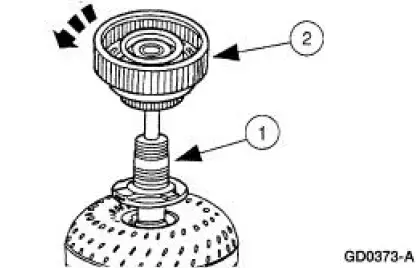
5. If interference exists, the stator front thrust washer may be worn, allowing the stator to hit the turbine. In such cases, a new or remanufactured torque converter must be installed.
- The converter crankshaft pilot should be checked for nicks or damaged surfaces that could cause interference when installing the torque converter into the crankshaft. Check the converter front impeller hub for nicks or sharp edges that would damage the pump seal.
 Torque Converter End Play Check
Special Tool(s)
Dial Indicator Gauge with
Holding Fixture
100-002 (TOOL-4201-C) or
equivalent
End Play Gauge, Torque
Converter
307-071 (T80L-7902-A) or
equivalent
...
 Transmission (ASSEMBLY)
Special Tool(s)
Dial Indicator Gauge with
Holding Fixture
100-002 (TOOL-4201-C)
Rubber Tip Air Nozzle
100-D009 (D93L-7000-A)
Alignment Gauge, TR Sensor
307-3 ...
Other materials:
Using sync with your media player
You can access and play music from your digital music player over
the vehicle’s speaker system using the system’s media menu or voice
commands. You can also sort and play your music by specific categories,
such as artists, albums, etc.
SYNC is capable of ...
Installation
1. Install the spring.
1. Position the spring and spring insulator in the front suspension lower
control arm.
2. Swing the arm into the fender well.
2. Position a jack stand under the front suspension lower control arm inboard
of the spring seat
and r ...
Safety Belt Buckle - Front Seat
Removal
Driver and passenger seat
1. Remove the front seat. For additional information, refer to Section.
2. Remove the nut and the safety belt buckle.
Driver seat only
3. Disconnect the safety belt buckle electrical connector.
Installation
1. To install, ...
