Ford Mustang (1999-2004) Service Manual: Assembly
All steering gears
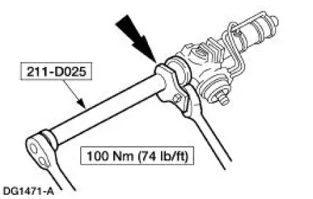
1. Install the steering gear in the special tools.
Steering gears equipped with travel restrictors
2. Install the travel restrictors.
- Install new travel restrictors as necessary.
All steering gears
3. CAUTION: Place the steering gear at the center position. Use a crowfoot on the flat of the rack gear to resist rotation and prevent damage to the steering gear during removal and installation of the front wheel spindle tie-rods.
Place the steering gear at the center position. Install a crowfoot on the flat of the steering gear.
Using the special tool install the front wheel spindle tie-rods.
4. Thoroughly clean the steering gear of any foreign material.
5. CAUTION: Use care not to damage the front suspension steering ball stud dust seals. If the front suspension steering ball stud dust seals are damaged, this will allow contamination into the steering gear and cause leakage.
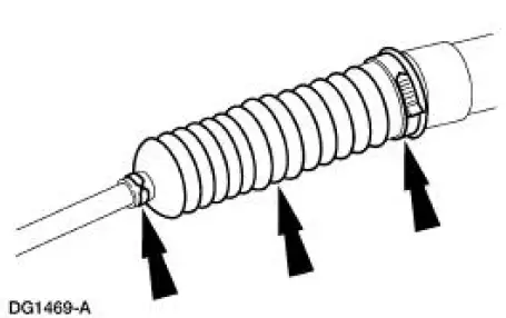
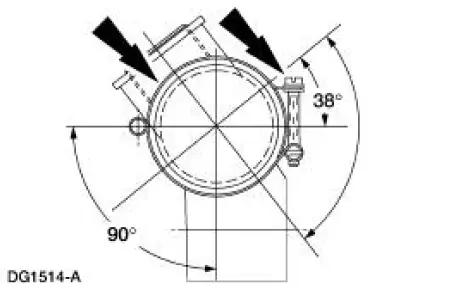
Install the front suspension steering ball stud dust seals and clamps.
- Position the front suspension steering ball stud seals and steering gear rack tubes as shown.
- Install new front suspension steering ball stud dust seals and clamps as necessary.
- To prevent the front suspension steering ball stud dust seals from twisting during toe adjustment, apply grease to the groove in the front wheel spindle tie-rods and uniformly to the inner-diameter of the front suspension steering ball stud dust seals.
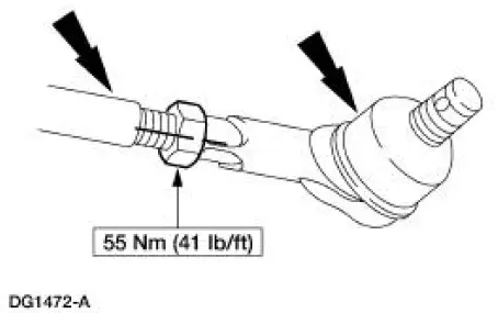
6. Install the nut and the tie-rods ends. Align the marks.
- Apply silicone dielectric compound to the front wheel spindle tie-rod threads.
7. Remove the steering gear from the special tools.
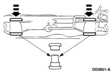
8. Install the steering gear mounting bracket housing insulators.
- Install new steering gear mounting bracket housing insulators as necessary.
- The large end of the metal sleeve must be positioned downward.
- Check that the mounting surfaces are clean and free of foreign material.
 Disassembly
NOTE: The steering gear is serviceable as either a long or short rack
assembly. This procedure covers
the removal and installation of the components not supplied with a short rack
assembly. On short ...
 Steering Column
General Specifications
Torque Specifications
...
Other materials:
Exhaust System (Diagnosis and Testing)
Symptom Chart
Condition
Possible Sources
Action
Noisy or
leaking
exhaust
Broken or loose
clamps, hangers or
isolators.
Punctures in the muffler
(5230).
Broken, loose or
missing exhaust
manifold fa ...
Hydraulic Brake Actuation (Description and Operation)
CAUTION: Blistering or swelling of rubber brake components may indicate
contamination
of the brake fluid by a petroleum based substance. New rubber components must be
installed
in the hydraulic brake system if contaminated and the entire hydraulic ...
Pinpoint Tests
NOTE: Reinstall or install new evaporative emission hose clamps
removed or damaged during testing
procedures.
PINPOINT TEST A: DTC P0442 SMALL LEAK IN EVAP SYSTEM
Test Step
Result / Action to Take
NOTE: Condition P0442 DTC set: less than 0.62 ...
