Ford Mustang (1999-2004) Service Manual: Dual Converter Y-Pipe - 3.8L
Removal
NOTE: The RH and LH catalytic converters are serviceable separately.
1. Raise and support the vehicle. For additional information, refer to Section.
2. CAUTION: When repairing the exhaust system or removing exhaust components, disconnect all heated oxygen sensors (HO2S) (9F472) and catalyst monitor sensors at the wiring connectors to prevent damage to the sensors and wiring harnesses.
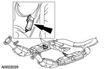
Disconnect the RH and LH HO2S connectors.
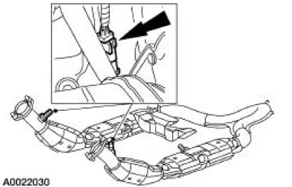
3. Disconnect the RH and LH catalyst monitor sensor connectors.
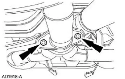
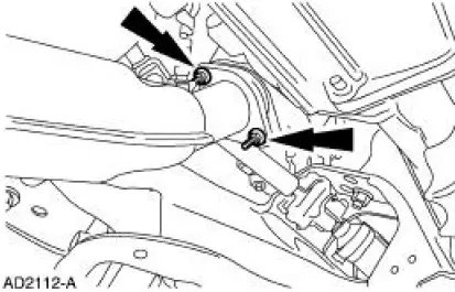
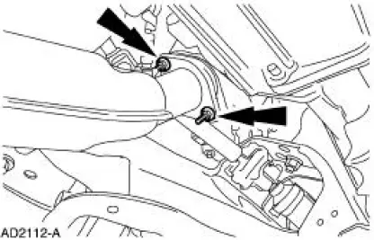
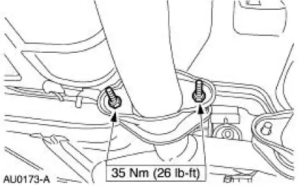
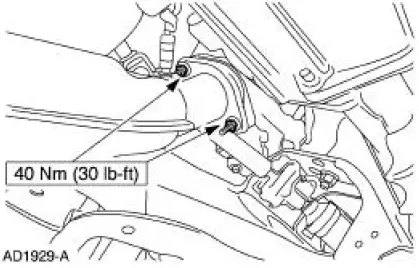
4. Remove the dual converter assembly nuts.
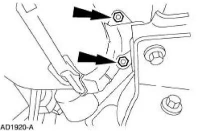
5. Remove the RH exhaust manifold flange nuts.
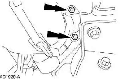
6. Remove the LH exhaust manifold flange nuts.
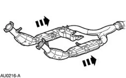
7. Remove the dual converter (5F250) assembly.
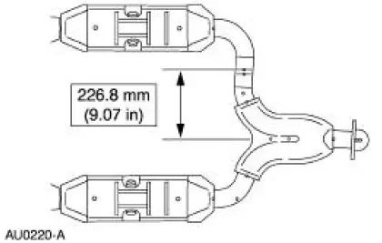
8. If necessary, use the two spot welds as a baseline, measure 226.8 mm (9.07 in) and cut the pipe.
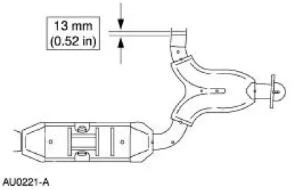
9. Remove 13 mm (0.52 in) from the LH dual converter.
Installation
1. Position the LH dual converter.
- Snug the LH converter-to-manifold nuts.
2. Position the RH dual converter pipe.
- Snug the RH converter-to-manifold nuts.
3. If necessary, position the LH and RH dual converter pipes into the sleeve and install the clamps.
Tighten the clamps to 55 Nm (41 lb-ft).
4. Install the dual converter assembly nuts.
5. Tighten the LH converter-to-manifold nuts.
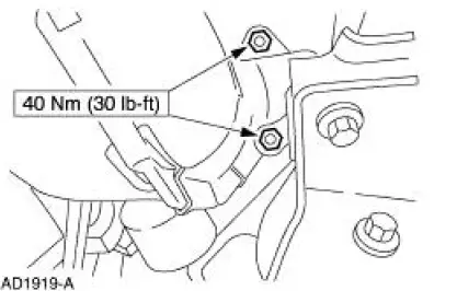
6. Tighten the RH converter-to-manifold nuts.
7. Connect the RH and LH HO2S connectors.
8. Connect the RH and LH catalyst monitor sensor connectors.
9. Lower the vehicle.
 Muffler - 4.6L (4V)
Removal and Installation
1. Raise and support the vehicle. For additional information, refer to
Section.
2. NOTE: RH side shown, LH side similar.
Remove the dual converter assembly nuts.
3. Remove ...
 Dual Converter H-Pipe - 4.6L (2V and 4V)
Removal
NOTE: The RH and LH catalytic converters are serviced separately.
1. Raise and support the vehicle. For additional information, refer to
Section.
2. CAUTION: When repairing exhaust system or ...
Other materials:
Principles of Operation
Battery Saver
The battery saver feature provides automatic shut-off of power to demand
and courtesy lamp circuitry.
When the generic electronic module (GEM) detects the ignition switch
circuits are in the key OFF or
removed ignition key positions, powe ...
Idle Air Control (IAC) Valve - Cobra
Removal and Installation
1. Disconnect the idle air control (IAC) valve electrical connector.
2. Remove the bolts, the IAC valve and the gasket.
3. NOTE: Install a new gasket if necessary.
To install, reverse the removal procedure. ...
Powertrain Control Module (PCM)
Removal
1. Disconnect the battery ground cable. For additional information,
refer to Section.
2. Remove the RH front door scuff plate.
3. Remove the RH cowl side trim panel.
Remove the pin-type retainer.
Remove the panel.
4. Disconnect ...
