Ford Mustang (1999-2004) Service Manual: Dual Converter H-Pipe - 4.6L (2V and 4V)
Removal
NOTE: The RH and LH catalytic converters are serviced separately.
1. Raise and support the vehicle. For additional information, refer to Section.
2. CAUTION: When repairing exhaust system or removing the exhaust components, disconnect all heated oxygen sensors (HO2S) (9F472) at the wiring connectors to prevent damage to the heated oxygen sensors and wiring harness.
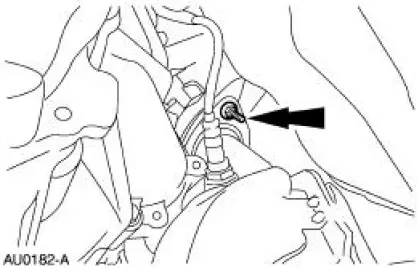
Disconnect the downstream RH and LH heated oxygen sensor connectors (9F472).
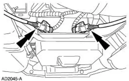
3. Disconnect the two upstream RH and LH catalyst monitor sensor connectors.

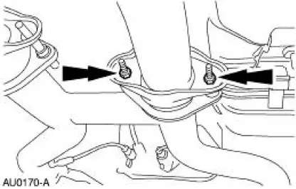
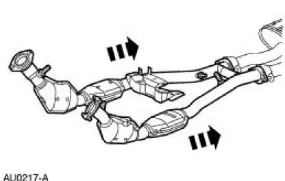
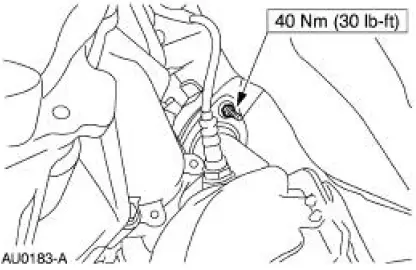
4. Remove the dual converter assembly nuts. (RH shown, LH similar.)
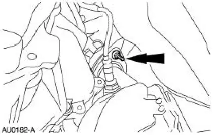
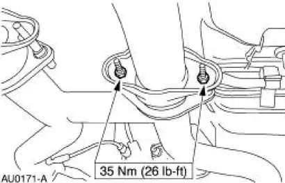
5. Remove the RH exhaust manifold flange nuts.
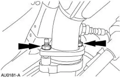
6. Remove the LH exhaust manifold flange nuts.
7. Remove the dual converter H-pipe.
8. If necessary, use the center of the LH flange as a baseline, measure 67 mm (2.68 in) and cut the cross-over pipe.
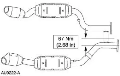
9. If necessary, use the center of the RH flange as a baseline, measure 83.9 mm (3.35 in) and cut the cross-over pipe.
Installation
1. Position the LH and RH dual converter pipe.
- Snug the converter-to-manifold nuts.
2. Position the muffler and install the dual converter assembly nuts. (RH shown, LH similar.)
3. If necessary, position the sleeve and clamps. Tighten the clamps to 55 Nm (41 lb-ft).
4. Tighten the four converter-to-manifold nuts.
5. Connect the two upstream RH and LH heated oxygen sensor connectors.
6. Connect the two downstream RH and LH catalyst monitor sensor connectors.
 Dual Converter Y-Pipe - 3.8L
Removal
NOTE: The RH and LH catalytic converters are serviceable separately.
1. Raise and support the vehicle. For additional information, refer to
Section.
2. CAUTION: When repairing the exhaust sys ...
 Fuel System
...
Other materials:
Removal
1. Remove the center instrument panel register.
2. Remove the screws.
3. Disconnect the connectors.
4. Using the special tool, disconnect the temperature control cable from the
control head.
5. Remove the nuts and disconnect the vacuum connector.
...
Removal
WARNING: Always wear safety glasses when repairing an air bag
supplemental restraint
system (SRS) vehicle and when handling an air bag module. This will
reduce the risk of injury
in the event of an accidental deployment.
WARNING: Carry a live air ...
General information
Have your vehicle serviced regularly to help maintain its roadworthiness
and resale value. There is a large network of Ford authorized dealers
who are there to help you with their professional servicing expertise.
We believe that their specially trained techn ...
