Ford Mustang (1999-2004) Service Manual: EGR System Components
The EGR system returns a portion of the exhaust gas to the intake manifold to reduce the combustion temperature. This results in lower nitrous oxide formation.
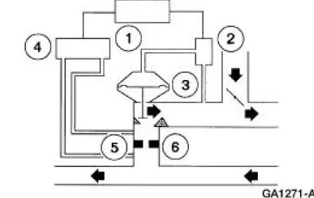
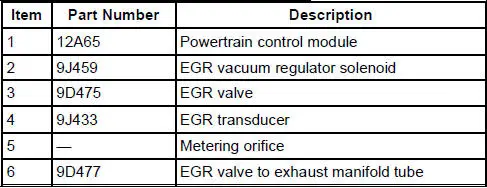
The powertrain control module (PCM) controls the EGR vacuum regulator solenoid . The EGR vacuum regulator solenoid controls the vacuum to the EGR valve. When the EGR valve opens, exhaust gas flows to the intake manifold. The EGR transducer measures the flow through the EGR valve to exhaust manifold tube and sends a signal to the powertrain control module. A metering orifice in the EGR valve to exhaust manifold tube restricts the flow rate when the EGR valve is open.
The PCV valve:
- controls the amount of ventilating air and blow-by gases going to the intake manifold.
- prevents a backfire from reaching the crankcase.
The EGR valve to exhaust manifold tube:
- connects the exhaust manifold to the EGR valve.
- has two tubes connecting to the EGR transducer for EGR flow monitoring.
The EGR transducer:
- monitors the EGR flow rate through the EGR valve to exhaust manifold tube.
- sends an EGR flow rate signal to the powertrain control module.
The EGR vacuum regulator solenoid uses input from the powertrain control module to change the EGR valve operation.
Engine Emission Control (DIAGNOSIS AND TESTING)
Refer to the Powertrain Control/Emissions Diagnosis (PC/ED) manual.
 Typical Vehicle Emission Control Information (VECI) Decal
The Vehicle Emission Control Information (VECI) decal shows:
the components of the emission control system.
the correct vacuum hose routing.
the color stripe of the vacuum hoses.
...
 Exhaust Gas Recirculation (EGR) Valve
Removal and Installation
NOTE: The 4.6L, 2V is shown. The 3.8L is similar.
1. Disconnect the vacuum hose.
2. Disconnect the EGR tube from the EGR valve.
3. Remove the two bolts, the EGR valve an ...
Other materials:
Disassembly
1. Remove the driveshaft (4602). For additional information, refer to
Driveshaft in this section.
2. CAUTION: Under no circumstances is the driveshaft assembly to be
clamped in the
jaws of a vise or similar holding fixture. Denting or localizing fracture ca ...
Apply Components
There are eight apply components used to drive or hold the planetary
gearset components.
Band-Overdrive
1. The overdrive band holds the reverse clutch drum stationary in fourth gear
and manual
2. This action
causes the reverse sun gear to be h ...
Pinpoint Test F: LFC 16/DTC B1888 - Passenger Air Bag Circuit Shorted to
Ground
Normal Operation
The restraints control module (RCM) checks for passenger air bag circuit
shorts to ground by
monitoring the voltage of circuits 607 (LB/OG) and 616 (PK/BK) at pins 6 and
7. If the RCM detects a
short to ground on either of these pins, i ...
