Ford Mustang (1999-2004) Service Manual: Electronic Leak Detection
Special Tool(s)
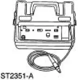 |
H10PM Refrigerant Leak Detector With Battery 216-00001 or equivalent |
CAUTION: Good ventilation is necessary in the area where electronic A/C leak testing is to be carried out. If the surrounding air is contaminated with refrigerant gas, the leak detector will indicate this gas all the time. Odors from other chemicals such as anti-freeze, diesel fuel, disc brake cleaner, or other cleaning solvents can cause the same problem. A fan, even in a wellventilated area, is very helpful in removing small traces of contamination from the air that might affect the leak detector.
1. NOTE: The system pressure should be between 413-551 kPa (60-80 psi) at 24C (75F) with the engine off.
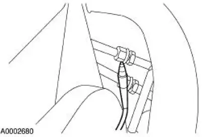
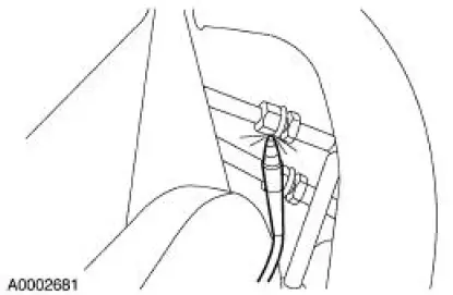
Leak test the refrigerant system using the Refrigerant Leak Detector. Follow the instructions included with the leak detector for handling and operation techniques.
2. If a leak is found, discharge and recover the refrigerant. For additional information, refer to Air Conditioning (A/C) System Recovery, Evacuation and Charging in this section.
- Repair the system.
- Test the system for normal operation.
 Manifold Gauge Set Connection
Special Tool(s)
R-134a Manifold Gauge Set
176-R032A or equivalent
1. Turn both valves on the R-134a Manifold Gauge Set clockwise to close the
low- and highpressure
hoses to the center ...
 Tracer Dye Leak Detection
Special Tool(s)
120 Watt 110 Volt UV Lamp
20C
164-R0721 or equivalent
NOTE: Ford Motor Company vehicles are produced with a permanent leak
tracer dye incorporated into
the A/C syste ...
Other materials:
Connecting Rod - Twist
1. Measure the connecting rod twist on a suitable alignment fixture.
Follow the instructions of the
fixture manufacturer. Verify the measurement is within specification.
Refer to the appropriate section in Group for the procedure.
If out of specificat ...
Wheel Hub or Axle Flange Face Runout
NOTE: If the axle shaft assembly is removed, check runout of the shaft
itself. The forged (unmachined)
part of the shaft is allowed to have as much as 3.0 mm (0.120 inch) runout. This
alone will not cause a
vibration condition.
1. Position the special tool ...
Wheel Hub or Axle Flange Bolt Circle Runout
NOTE: The brake discs must be removed to carry out all runout
measurements.
1. Position the special tool perpendicular to the wheel hub or axle flange bolt,
as close to the hub
or flange face as possible. Zero the indicator to allow the pointer to deflect
...
