Ford Mustang (1999-2004) Service Manual: Climate Control System - General Information
General Specifications
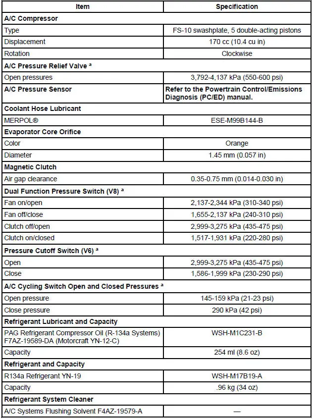
a - Manifold gauge set pressures may vary slightly depending on the distance between the service gauge port valve and the A/C pressure relief valve, the A/C cycling switch, the pressure cutoff switch (V6), and the dual function pressure switch (V8) location.
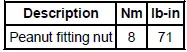
Torque Specifications
- Climate Control System (Description and Operation)
- Climate Control System (Diagnosis and Testing)
- Air Conditioning (A/C) System Check - Retail Procedure
- Spring Lock Coupling
- Heater Hose Coupling
- Air Conditioning Line (Peanut) Fitting
- Refrigerant System Tests
- Manifold Gauge Set Connection
- Electronic Leak Detection
- Tracer Dye Leak Detection
- Air Conditioning (A/C) System Flushing
- Air Conditioning (A/C) System Recovery, Evacuation and Charging
- Refrigerant System Filtering Following Air Conditioning (A/C) Component Installation
- Refrigerant Oil Adding
- Inspection and Assembly Requirements - Following an A/C Compressor Failure
- Refrigerant Identification Testing
- Contaminated Refrigerant Handling
- Vacuum Hose Repair - Mini-Tube

 Climate Control System (Description and Operation)
WARNING: To avoid accidental deployment and possible injury, the air
bag system
backup power supply must be depleted before repairing any climate control
components. To
deplete the backup power supp ...
Other materials:
Belt Minder Deactivating/Activating
Preparation
1. Before deactivating/activating the belt minder, set the parking
brake.
2. Place the gearshift in P (Park) (automatic transmission) or the
neutral position (manual
transmission).
3. Place the ignition switch in the OFF position.
...
Multifunction Switch
Removal
1. Disconnect the battery ground cable.
2. Remove the ignition switch lock cylinder.
1. Insert the ignition key into the ignition switch lock cylinder and
turn to RUN position.
2. Push the ignition switch lock cylinder release tab with a p ...
Inspection and Verification
1. Verify the customer concern.
2. Visually inspect for obvious signs of mechanical and electrical damage.
Visual Inspection Chart
Mechanical
Electrical
Fuel tank
Engine coolant level
Accessory drive belt
Engine oil level
Par ...
