Ford Mustang (1999-2004) Service Manual: Manifold Gauge Set Connection
Special Tool(s)
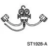 |
R-134a Manifold Gauge Set 176-R032A or equivalent |
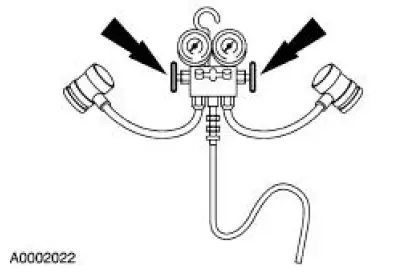
1. Turn both valves on the R-134a Manifold Gauge Set clockwise to close the low- and highpressure hoses to the center manifold and center hose.
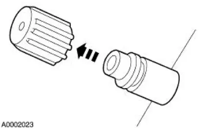
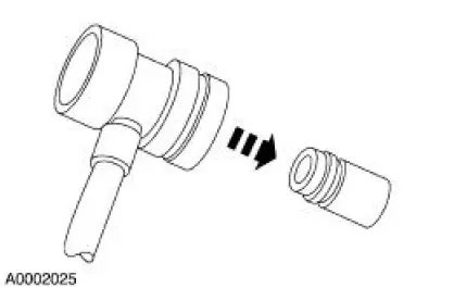
2. Remove the A/C charging valve cap (19D702) from the low-pressure service gauge port valve.
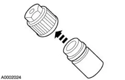
3. Remove the A/C charging valve cap from the high-pressure service gauge port valve.
4. Connect the R-134a Manifold Gauge Set low-pressure hose and the R-134a low side quick disconnect to the low-pressure service gauge port valve.
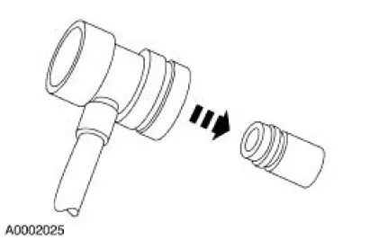
5. Connect the R-134a Manifold Gauge Set high-pressure hose and the R-134a high side quick disconnect to the high-pressure service gauge port valve.
 Refrigerant System Tests
Special Tool(s)
R-134a Manifold Gauge Set
176-R032A or equivalent
1. Connect the R-134a Manifold Gauge Set. For additional information, refer
to Manifold Gauge
Set Connection in this ...
 Electronic Leak Detection
Special Tool(s)
H10PM Refrigerant Leak
Detector With Battery
216-00001 or equivalent
CAUTION: Good ventilation is necessary in the area where electronic A/C
leak testing is to
be ca ...
Other materials:
Adjusting the headlamps
The headlamps on your vehicle are properly aimed at the assembly plant.
If your vehicle has been in an accident, an authorized dealer should
check the alignment of your headlamps.
Vertical Aim Adjustment
1. Park the vehicle directly in front of a wall or scre ...
Wipers and Washers (Diagnosis and Testing)
Refer to Wiring Diagrams Cell 59 , Generic Electronic Module for
schematic and connector
information.
Refer to Wiring Diagrams Cell 81 , Interval Wiper/Washer for schematic
and connector information.
Special Tool(s)
Alternator, Regulato ...
Inspection and Verification
1. Verify the customer concern.
2. Visually inspect for obvious signs of mechanical and electrical damage.
Visual Inspection Chart
Mechanical
Electrical
Fuel tank
Engine coolant level
Accessory drive belt
Engine oil level
Par ...
