Ford Mustang (1999-2004) Service Manual: Engine (Assembly)
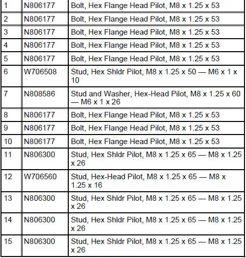
Special Tool(s)
|
|
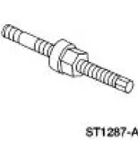
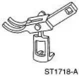
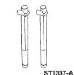
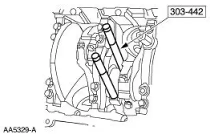
Guides, Connecting Rod 303-442 (T93P-6136-A) |
 |
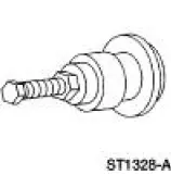
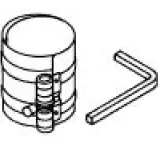
Installer, Crankshaft Vibration Damper 303-102 (T74P-6316-B) |
 |
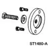
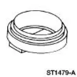
Installer, Front Cover Oil Seal 303-335 (T88T-6701-A) |
 |
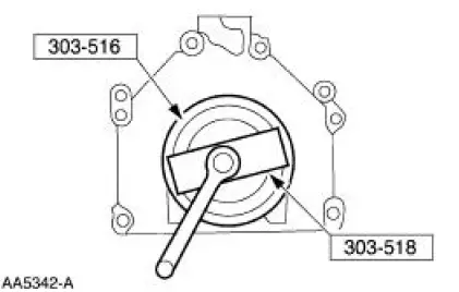
Installer, Crankshaft Rear Oil Seal 303-518 (T95P-6701-DH) |
 |
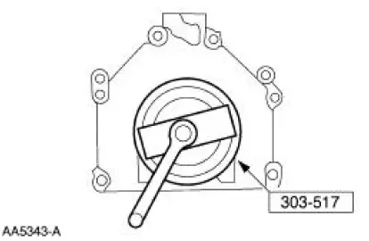
Installer, Crankshaft Rear Oil Slinger 303-517 (T95P-6701-CH) |
 |
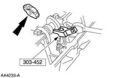
Compressor, Valve Spring (Intake) 303-452 (T93P-6565-AR) |
 |
Compressor, Valve Spring (Exhaust) 303-567 (T97P-6565-AH) |
 |
Installer, Crankshaft Rear Oil Seal 303-516 (T95P-6701-BH) |
 |
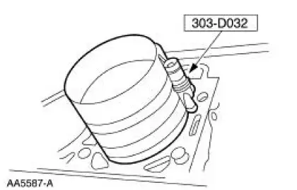
Compressor, Piston Ring 303-D032 (D81L-6002-C) or equivalent |
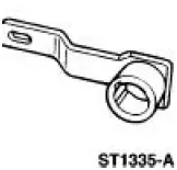 |
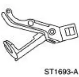
Holding Tool, Crankshaft 303-448 (T93P-6303-A) |
Material
| Item | Specification |
| Metal Surface Cleaner F4AZ-19A536-RA or equivalent | WSE-M5B392- A |
| Silicone Gasket and Sealant F7AZ-19554-EA or equivalent | WSE-M4G323- A4 |
| Super Premium SAE 5W-20 Engine Oil XO-5W20-QSP or equivalent | WSS-M2C153- H |
| Motorcraft Premium Gold Engine Coolant VC-7-A (in Oregon VC-7-B) (yellow color) | WSS-M97B51- A1 |
Assembly
All vehicles
1. Record the main bearing code found on the front of the engine block.
2. Record the main bearing code found on the back of the crankshaft.
3. Using the data recorded earlier and the Bearing Select Fit Chart, Standard Bearings Chart determine the required bearing grade for each main bearing.
- Read the first letter of the engine block main bearing code and the first letter of the crankshaft main bearing code.
- Read down the column below the engine block main bearing code letter, and across the row next to the crankshaft main bearing code letter, until the two intersect. This is the required bearing grade for the number one crankshaft main bearing.
- As an example, if the engine block code letter is "F" and the crankshaft code letter is "D," the correct bearing grade for this main bearing is "2."
- Repeat this process for the remaining four main bearings.
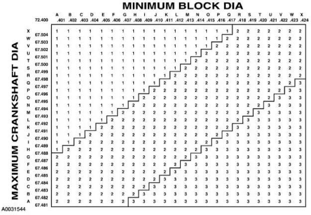
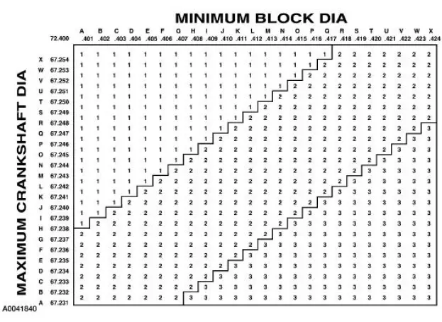
4. If oversize bearings are being used, use the procedure in the previous step and the Bearing Select Fit Chart, Oversize Bearing Chart to determine the required grade for each main bearing.
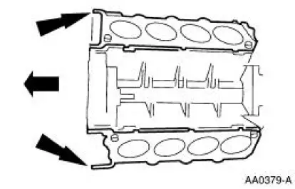
NOTE: Before assembling the cylinder block, all sealing surfaces must be free from chips, dirt, paint and foreign material. Also, make sure the coolant and oil passages are clear.
5. Install the upper main bearings into the cylinder block and the lower main bearing into the crankshaft main bearing caps. Lubricate the main bearings with clean engine oil.
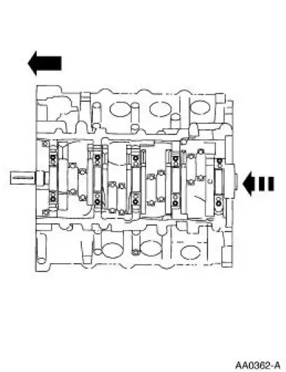
6. Install the crankshaft into the cylinder block.
7. CAUTION: Make sure the coated side of the thrust washer with the 5-mm wide oil grooves faces the crankshaft thrust surface.
Push the crankshaft rearward and install the crankshaft thrust washer at the back of the No. 5 main boss.
8. Loosely install the main bearing caps and the bolts.
9. Push the crankshaft forward to seat the crankshaft thrust washer and hold the crankshaft in the forward position.
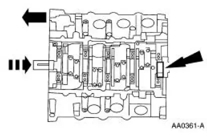
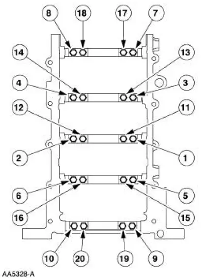
10. Tighten bolts 1-20 in sequence shown in four stages.
- Stage 1: tighten to 10 Nm (89 lb-in).
- Stage 2: tighten to 25 Nm (18 lb-ft).
- Stage 3: tighten to 40 Nm (30 lb-ft).
- Stage 4: tighten an additional 90 degrees.
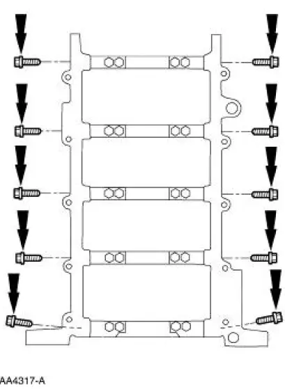
11. Install and tighten the cross-mounted bolts in two stages.
- Stage 1: tighten to 40 Nm (30 lb-ft).
- Stage 2: tighten an additional 90 degrees.
12. Check the crankshaft end play. For additional information, refer to Section.
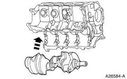
13. CAUTION: Do not scratch the cylinder walls or crankshaft journals with the connecting rod.
NOTE: Make sure that the piston arrow is facing forward.
NOTE: Lubricate the piston rings, cylinder walls and connecting rod bearings with clean engine oil.
Using the special tool push the pistons through the top of the cylinder block.
14. CAUTION: Do not scratch the cylinder walls or the crankshaft journals with the connecting rod.
NOTE: Make sure the crankshaft is at T.D.C.
Using the special tool, install the connecting rod assemblies.
15. NOTE: The rod bearing cap bolts are torque-to-yield. Install new bolts each time they are serviced.
Install the connecting rod bearing caps and bolts and tighten in three stages.
- Stage 1: tighten to 25 Nm (18 lb-ft).
- Stage 2: tighten to 45 Nm (33 lb-ft).
- Stage 3: tighten an additional 90 degrees.
16. Check the connecting rod bearing clearance. For additional information, refer to Section.
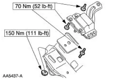
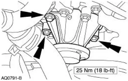
17. Install the LH engine mount.
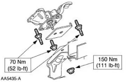
18. Install the RH engine mount.
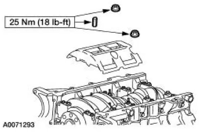
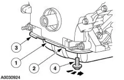
19. Install the nuts and the windage tray.
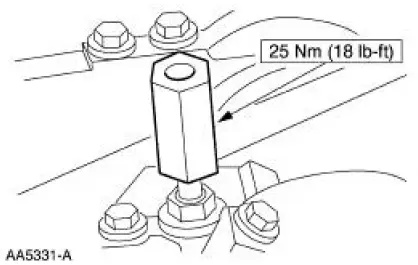
20. Install and tighten the oil pump screen spacer.
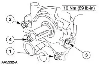
21. Position the oil pump and tighten the bolts in the sequence shown.
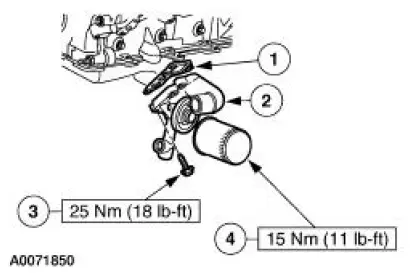
22. NOTE: Install a new O-ring if necessary.
Install the oil pump screen cover and tube.
23. Install the cylinder head gaskets.
24. CAUTION: The camshafts must be positioned so the camshaft keyway is 90 degrees from the valve cover gasket surface to avoid damage to valves and pistons during timing procedures.
Make sure the camshaft timing sprockets are positioned correctly.
25. NOTE: The LH is shown; the RH is similar.
NOTE: Lubricate the bolt heads and threads. Use clean engine oil.
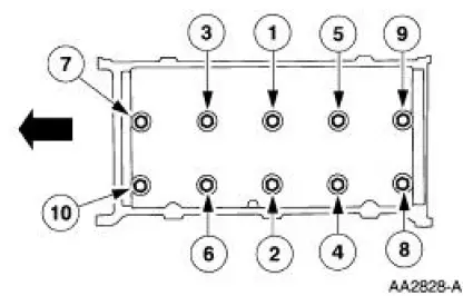
Install the LH and RH cylinder heads and tighten the bolts in six stages in the sequence shown.
- Stage 1: tighten to 40 Nm (30 lb-ft).
- Stage 2: tighten an additional 90 degrees.
- Stage 3: loosen the bolts a minimum of one full turn.
- Stage 4: tighten to 40 Nm (30 lb-ft).
- Stage 5: tighten an additional 90 degrees.
- Stage 6: tighten an additional 90 degrees.
26. CAUTION: Timing chain procedures must be followed exactly or damage to valves and pistons will result.
Compress the tensioner plunger, using a vise.
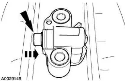
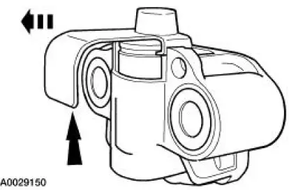
27. Install a retaining clip on the tensioner to hold the plunger in during installation.
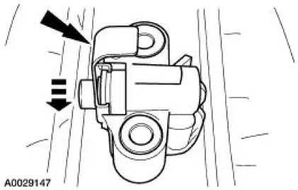
28. Remove the tensioner from the vise.
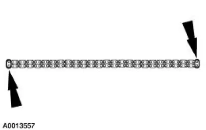
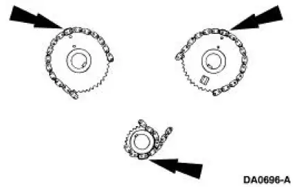
29. If the copper links are not visible, mark two links on one end and one link on the other end, and use as timing marks.
30. Install the timing chain guides.
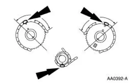
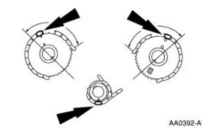
31. Rotate the LH camshaft timing sprocket until the timing mark is approximately at the 12 o'clock position. Rotate the RH camshaft timing sprocket until the timing mark is at approximately 11 o'clock position.
32. CAUTION: Unless otherwise instructed, at no time when the timing chains are removed and the cylinder heads are installed is the crankshaft or camshaft to be rotated.
Severe piston and valve damage will occur.
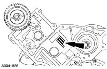
CAUTION: Rotate the crankshaft counterclockwise only. Do not rotate past position shown or severe piston and/or valve damage will occur.
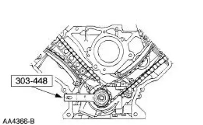
Using the special tool, position the crankshaft.
Remove the special tool.
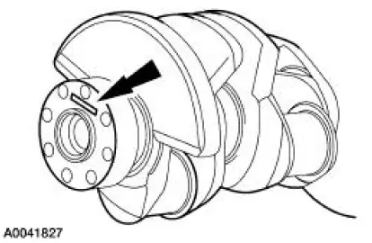
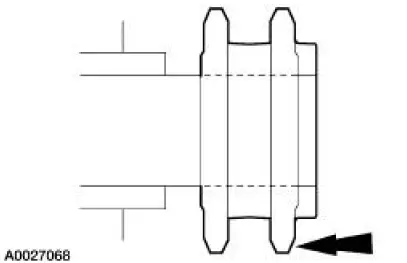
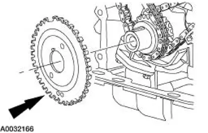
33. Install the crankshaft sprocket with the flange facing forward.
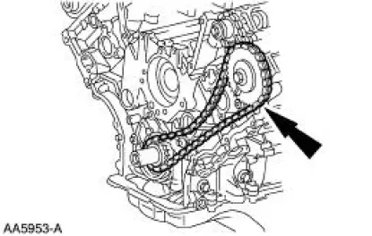
34. Install the LH and RH timing chain onto the crankshaft sprocket, aligning the one copper (or marked) link on the timing chain with the slot on the crankshaft sprocket.
35. NOTE: If necessary, adjust the camshaft sprocket slightly to obtain timing mark alignment.
Position the RH timing chain on the camshaft sprocket. Make sure the two copper-colored links align with the camshaft sprocket timing mark.
36. As a post-check, verify correct alignment of all timing marks.
37. Position the LH and RH timing chain tensioner arms on the dowel pins. Position the timing chain tensioner assemblies, and install the bolts.
38. Remove the retaining clips from the timing chain tensioners.
39. Position the crankshaft sensor ring on the crankshaft.
40. Install the oil pan and gasket and loosely install the bolts.
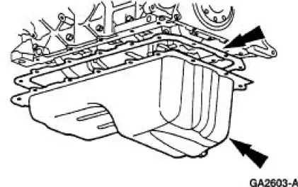
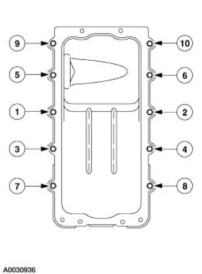
41. Tighten the bolts in the sequence shown.
- Tighten to 20 Nm (15 lb-ft).
- Rotate an additional 60 degrees.
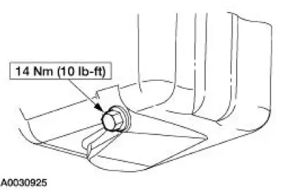
42. Install the drain plugs
43. NOTE: If the engine front cover is not secured within four minutes, the sealant must be removed and the sealing area cleaned with metal surface cleaner. Allow to dry until there is no sign of wetness, or four minutes, whichever is longer. Failure to follow this procedure can result in future oil leakage.
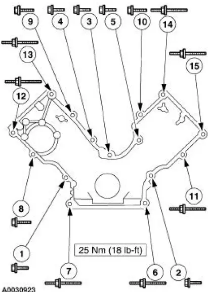
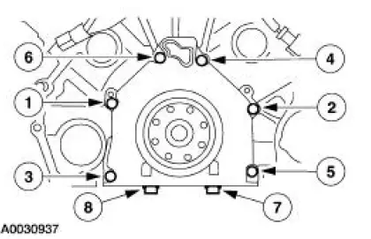
Apply silicone gasket and sealant in the locations shown.
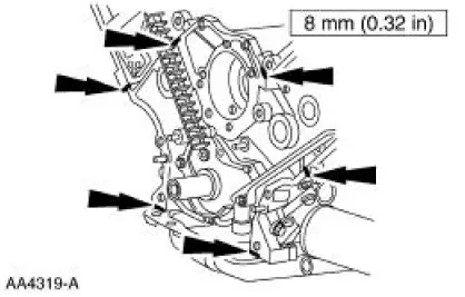
44. Install the engine front cover.

45. Tighten the four oil pan bolts in the sequence shown.
- Stage 1: Tighten to 2 Nm (18 lb-in).
- Stage 2: Tighten to 20 Nm (15 lb-ft).
- Stage 3: Tighten an additional 60 degrees.
46. Install oil filter adapter.
1. Position the gasket.
2. Position the oil filter adapter.
3. Tighten the bolts.
4. Install a new oil filter.
47. Using the special tool, install the 32 roller followers.
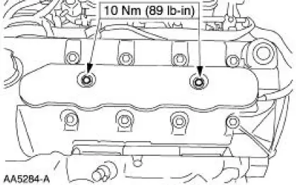
48. NOTE: If the valve cover is not secured within four minutes, the sealant must be removed and the sealing area cleaned with metal surface cleaner. Allow to dry until there is no sign of wetness, or four minutes, whichever is longer. Failure to follow this procedure can result in future oil leakage.
Apply silicone gasket and sealant in the locations shown.
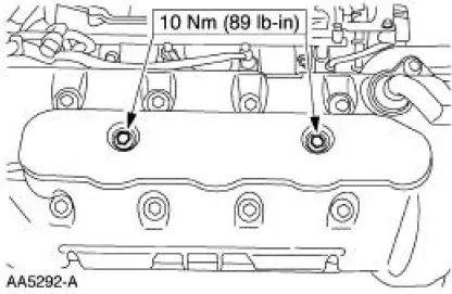
49. NOTE: The RH is shown; the LH is similar.
Install the valve covers and tighten the bolts in the sequence shown.
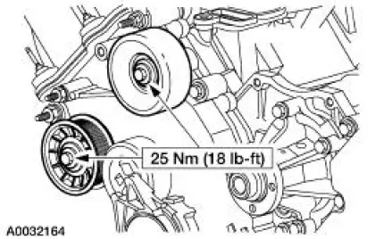
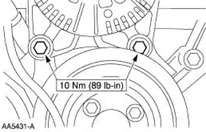
50. Install the belt idler pulleys.
51. Lubricate the front oil seal and the engine front cover with clean engine oil.
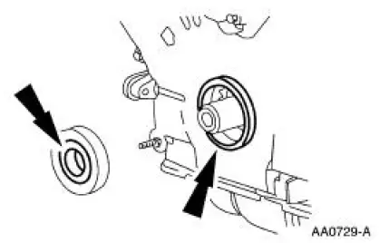
52. Using the special tool, install the front oil seal.
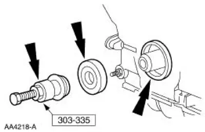
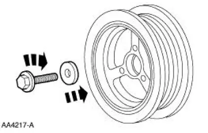
53. Apply silicone gasket and sealant to the woodruff key on the crankshaft pulley.
54. Using the special tool, install the crankshaft pulley.
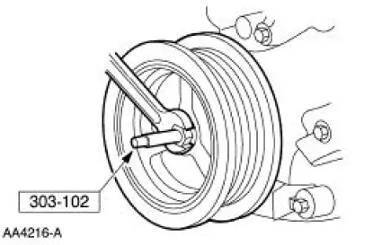
55. Install the crankshaft pulley and tighten the bolt in four stages.
- Stage 1: tighten to 90 Nm (66 lb-ft).
- Stage 2: loosen the bolt one full turn.
- Stage 3: tighten to 50 Nm (37 lb-ft).
- Stage 4: tighten an additional 90 degrees.
56. NOTE: Lubricate the O-ring seal with clean engine oil.
Install the coolant pump.
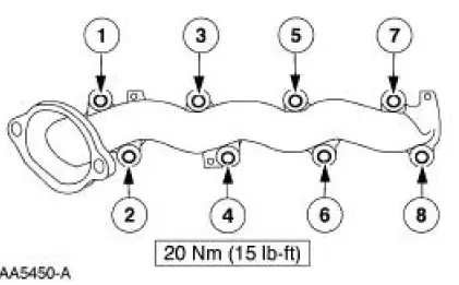
57. NOTE: The RH is shown; the LH is similar. Use new gaskets when installing the exhaust manifolds.
Install the exhaust manifold.
58. Install the knock sensors.
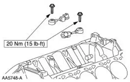
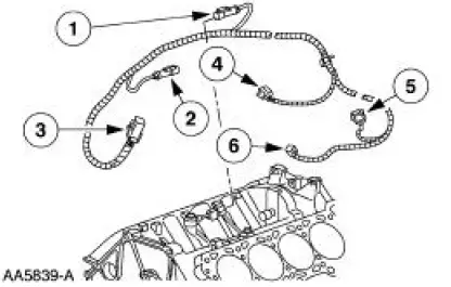
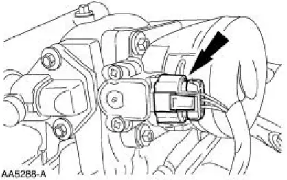
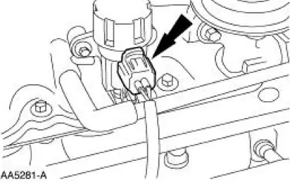
59. Install the knock sensor wiring harness.
1. LH knock sensor electrical connector
2. RH knock sensor electrical connector
3. Engine control sensor electrical connector
4. Fuel injector electrical connector
5. A/C compressor electrical connector
6. CKP sensor electrical connector
60. Install the lower intake manifold.
- Position the gaskets.
- Install the intake manifold and tighten the bolts in the sequence shown.
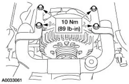
61. Install the generator.
62. Install the upper generator support bracket and coolant bypass tube.
- Install the upper generator support bracket.
- Install the coolant bypass tube.
- Install the bolts.
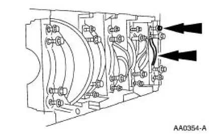
63. Install the eight ignition coils.
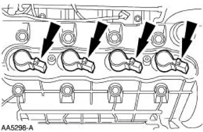
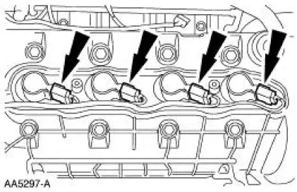
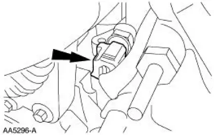
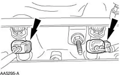
64. Connect the eight ignition coils.
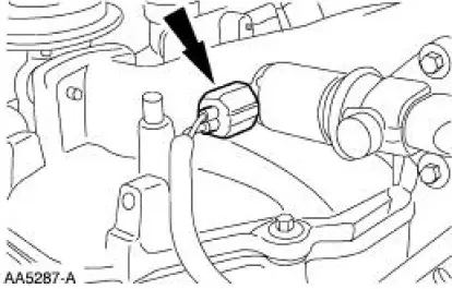
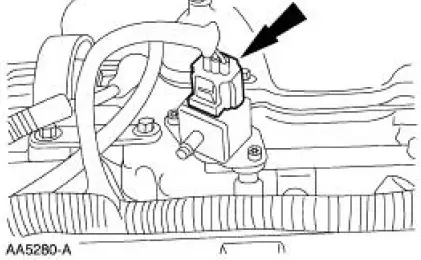
65. Connect the engine coolant temperature (ECT) sensor.
66. Connect the eight fuel injectors.
67. Install the RH ignition coil cover.
68. NOTE: The fastener at location five is a stud.
Install the gasket and the upper intake.
69. Connect the throttle position (TP) sensor electrical connector.
70. Connect the idle air control (IAC) valve electrical connector.
71. Connect the generator wiring.
72. Install the LH coil cover.
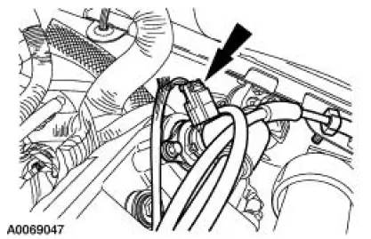
73. Connect the EGR vacuum regulator (EVR) electrical connector.
74. Connect the fuel pressure sensor electrical connector.
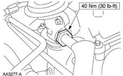
75. Connect the EGR tube to the exhaust manifold.
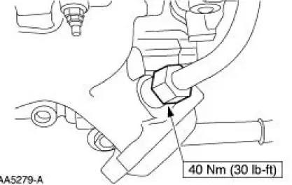
76. Connect the EGR tube to the EGR valve.
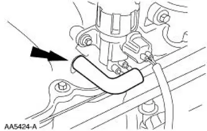
77. Install the PCV valve hose and connect the electical connector.
78. Connect the PCV valve tube to the upper intake manifold.
79. Install the special tool.
80. Remove the engine from the stand.
81. NOTE: If not secured within four minutes, the sealant must be removed and the sealing area cleaned with metal surface cleaner. Allow to dry until there is no sign of wetness, or four minutes, whichever is longer. Failure to follow this procedure can result in future oil leakage.
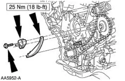
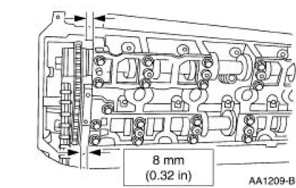
Apply a 4 mm (0.16 in) bead of silicone gasket and sealant around the rear oil seal retainer plate sealing surface. Also apply a bead of silicone gasket and sealant at the junction where the cylinder block, oil pan and rear oil seal retainer plate meet.
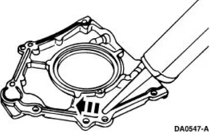
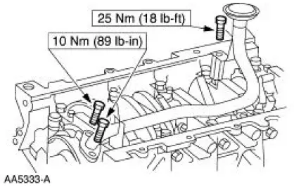
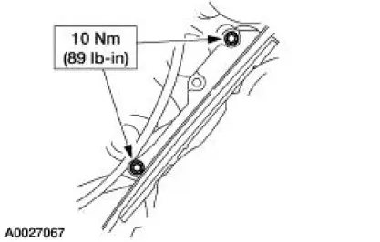
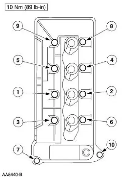
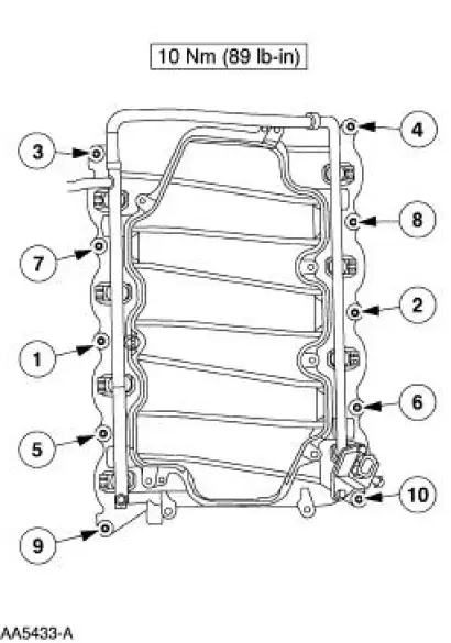
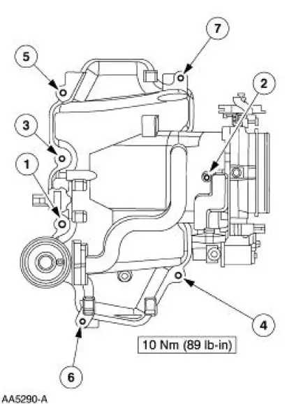
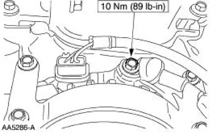
82. Install the rear oil seal retainer plate. Tighten the bolts in the sequence shown.
- Tighten the bolts to 1-6 to 10 Nm (89 lb-in).
- Hand-tighten bolts 7 and 8.
- Tighten bolts 7 and 8 to 20 Nm (15 lb-ft).
- Tighten bolts 7 and 8 an additional 60 degrees.
83. Using the special tool, install the crankshaft rear main seal.
84. Using the special tools, install the crankshaft oil slinger.
Automatic transmission vehicles
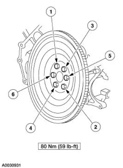
85. Install the flexplate and install the bolts in the sequence shown.
Manual transmission vehicles
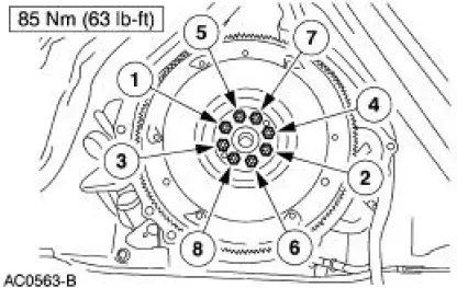
86. Install the flywheel and the bolts in the sequence shown.
87. Install the clutch and pressure plate. For additional information, refer to Section.
 Piston - Pin Connecting Rod, Floating Pin
Material
Item
Specification
SAE 5W-20 Premium Synthetic
Blend Engine Oil
XO-5W20-QSP
WSS-M2C153-
H
Disassembly
1. Remove the clips.
2. Remove the piston pin from the piston ...
 Engine (Installation)
Special Tool(s)
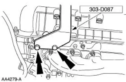
Lifting Bracket, Engine
303-D087 (D93P-6001-A1)
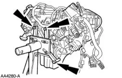
Lifting Bracket, Engine
303-D088 (D93P-6001-A2)
Installer Set, Teflon Seal
211-D027 (D90P-35 ...
Other materials:
Reporting safety defects (U.S. only)
If you believe that your vehicle has
a defect which could cause a crash
or could cause injury or death, you
should immediately inform the
National Highway Traffic Safety
Administration (NHTSA) in addition to notifying Ford Motor Company.
If NHTSA receives si ...
Getting the services you need
Warranty repairs to your vehicle must be performed by an authorized
dealer. While any authorized dealer handling your vehicle line will
provide warranty service, we recommend you return to your selling
authorized dealer who wants to ensure your continued satis ...
Safety Belt Maintenance
WARNING: All safety belt assemblies include retractors, buckles, front
seat belt buckle
support assemblies (slide bar, if so equipped), shoulder belt height adjuster
(if equipped), child
safety seat tether bracket assemblies (if equipped) and attaching hardw ...
