Ford Mustang (1999-2004) Service Manual: Engine (Disassembly)
Special Tool(s)
|
|
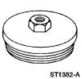
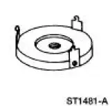
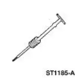
Impact Slide Hammer 100-001 (T50T-100-A) |
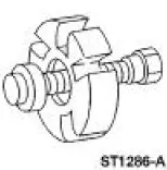 |
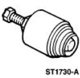
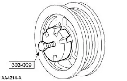
Remover, Crankshaft Vibration Damper 303-009 (T58P-6316-D) |
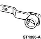 |
Holding Tool, Crankshaft 303-448 (T93P-6303-A) |
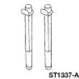 |
Guides, Connecting Rod 303-442 (T93P-6136-A) |
 |
Remover, Crankshaft Rear Oil Seal 303-519 (T95P-6701-EH) |
 |
Remover, Crankshaft Rear Oil Slinger 303-514 (T95P-6701-AH) |
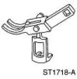 |
Compressor, Valve Spring (Intake) 303-452 (T93P-6565-AR) |
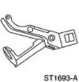 |
Compressor, Valve Spring (Exhaust) 303-567 (T97P-6565-AH) |
 |
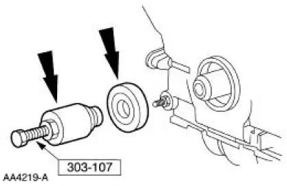
Remover, Crankshaft Front Oil Seal 303-107 (T74P-6700-A) |
Disassembly
Manual transmission vehicles
1. Remove the clutch and pressure plate. For additional information, refer to Section.
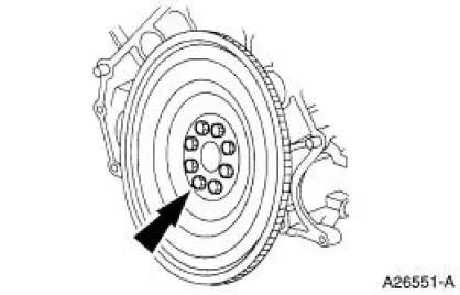
2. Remove the flywheel.
Automatic transmission vehicles
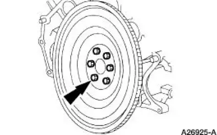
3. Remove the flexplate. For additional information, refer to Flexplate in this section.
All vehicles
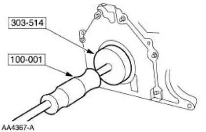
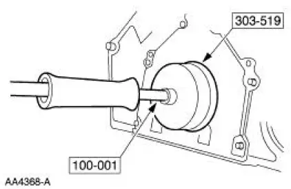
4. Using the special tool, remove the rear oil slinger.
5. Using the special tool, remove the rear main seal.
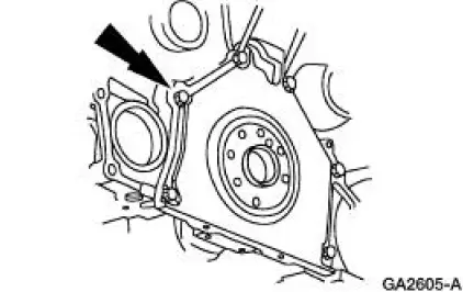
6. Remove the rear seal retainer plate.
7. Mount the engine on a work stand.
8. Remove the special tools.
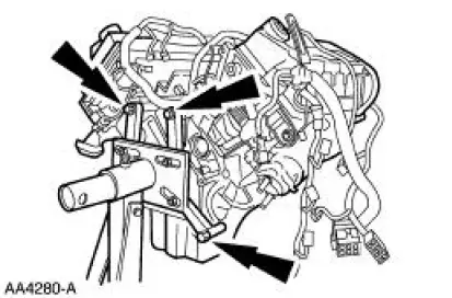
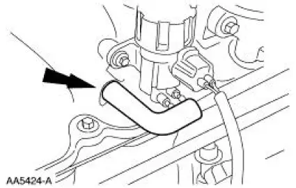
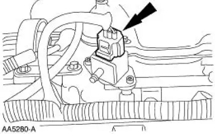
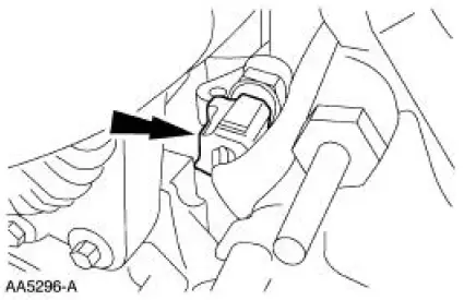
9. Disconnect the positive crankcase ventilation (PCV) tube.
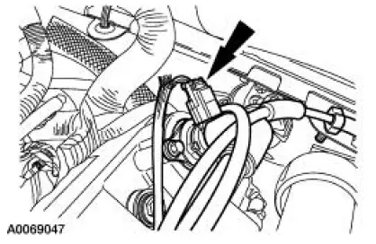
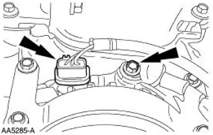
10. Remove the PCV valve tube and electrical connector.
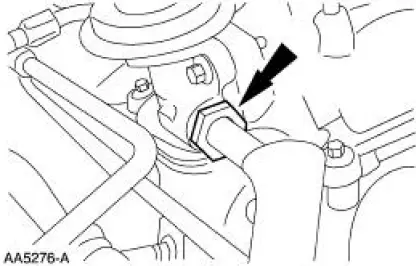
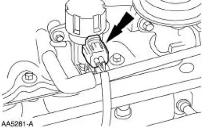
11. Disconnect the exhaust gas recirculation (EGR) tube from the EGR valve.
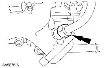
12. Disconnect the EGR tube from the exhaust manifold.
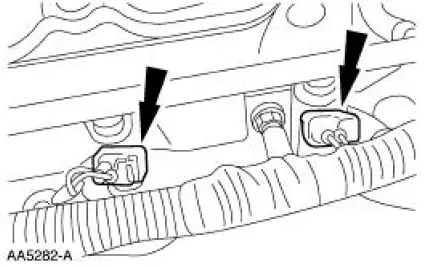
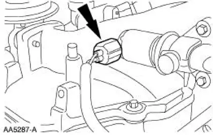
13. Disconnect the fuel pressure damper electrical connector.
14. Disconnect the EGR vacuum regulator electrical connector.
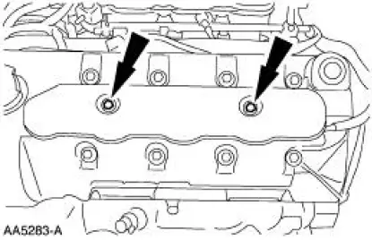
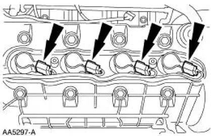
15. Disconnect the four LH fuel injector electrical connectors.
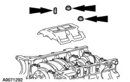
16. Remove the LH coil cover.
17. Disconnect the generator.
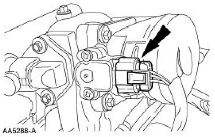
18. Disconnect the idle air control (IAC) valve electrical connector.
19. Disconnect the throttle position (TP) sensor electrical connector.
20. Remove the bolts and the upper intake manifold.
21. Remove the upper intake manifold gasket.
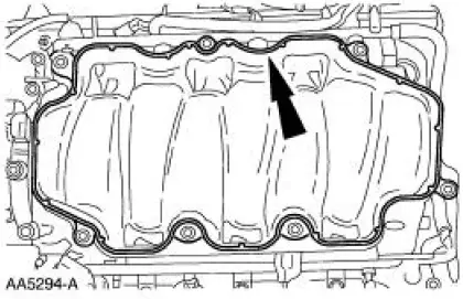
- Clean and inspect the sealing surfaces.
22. Remove the RH coil cover.
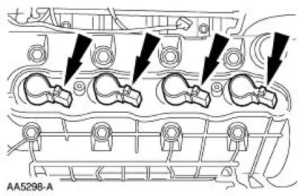
23. Disconnect the LH ignition coils.
24. Disconnect the four RH fuel injector electrical connectors.
25. Disconnect the engine coolant temperature (ECT) sensor.
26. Disconnect the RH ignition coils.
27. Remove the eight ignition coils.
28. Remove the bracket from the accessory drive belt tensioner.
29. Remove the accessory drive belt.
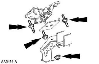
30. Remove the coolant bypass tube and upper generator support bracket.
- Remove the bolts.
- Remove the coolant bypass tube.
- Remove the upper generator support bracket.
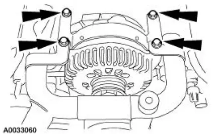
31. Remove the generator.
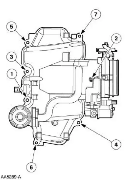
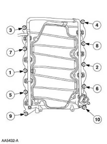
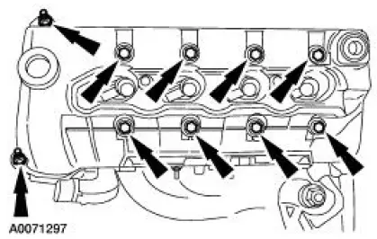
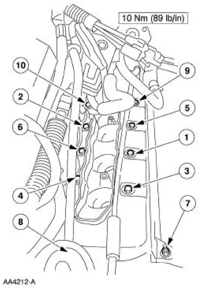
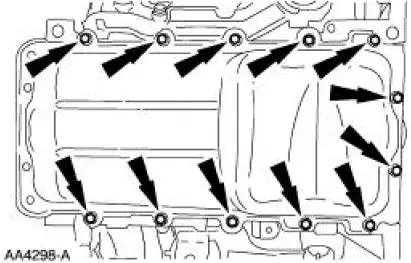
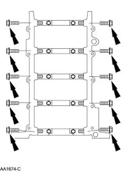
32. Remove the eight bolts and the two studs in the sequence shown. Remove the lower intake manifold.
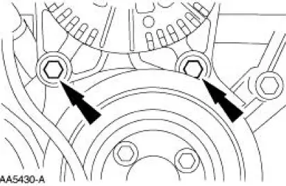
33. Remove the bolts and the coolant pump pulley.
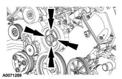
34. Remove the coolant pump from the cylinder block.
- Remove the bolts.
- Inspect and clean the sealing surfaces.
35. Remove the bolt.
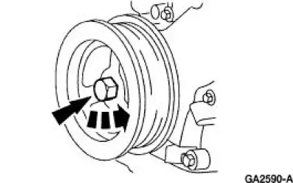
36. Using the special tool, remove the crankshaft pulley.
37. Using the special tool, remove the crankshaft front seal.
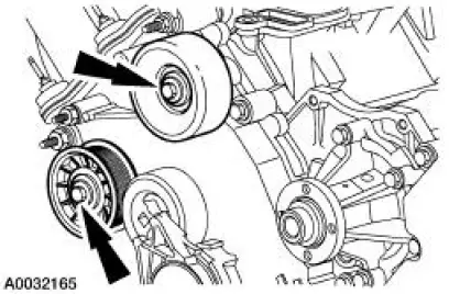
38. Remove the belt idler pulleys.
39. Remove the bolts and the LH valve cover.
40. Remove the bolts and the RH valve cover.
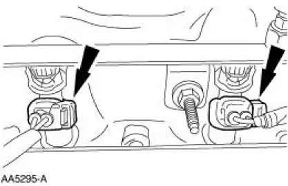
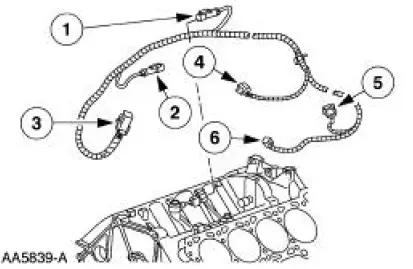
41. Remove the knock sensor wiring harness.
1. LH knock sensor electrical connector.
2. RH knock sensor electrical connector.
3. Engine control sensor electrical connector.
4. Fuel injector electrical connector.
5. A/C compressor electrical connector.
6. Crankshaft position sensor (CKP) electrical connector.
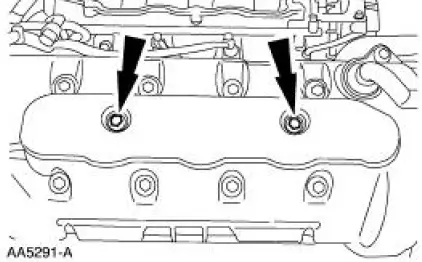
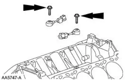
42. Remove the knock sensors.
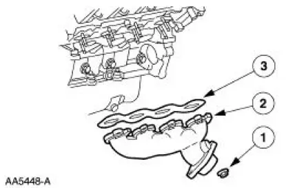
43. NOTE: LH side is shown; RH side is similar.
Remove the exhaust manifolds.
1. Remove the nuts.
2. Remove the LH and RH exhaust manifolds.
3. Remove the exhaust manifold gaskets.
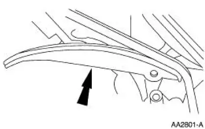
44. Remove the four bolts.
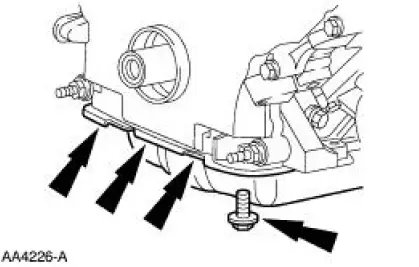
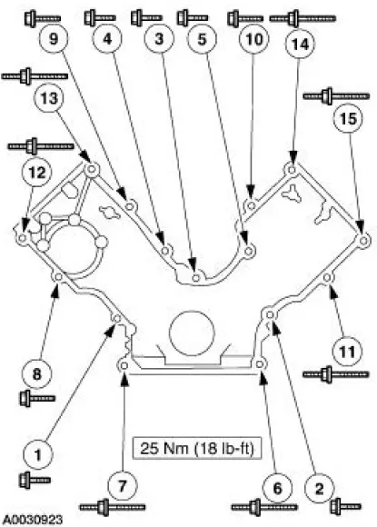
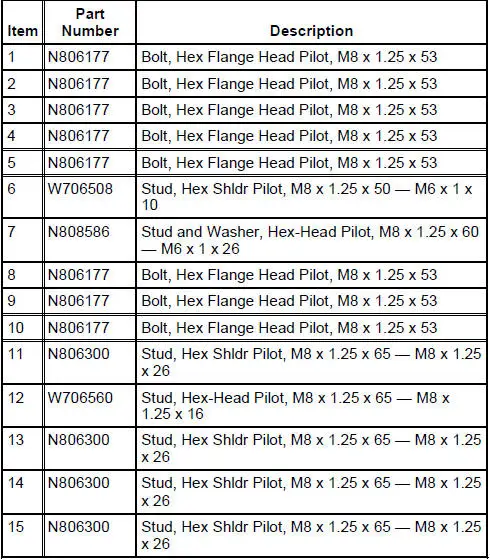
45. Remove the engine front cover.
46. NOTE: Be careful when removing the gasket. It is reusable if not damaged.
Remove the oil pan and the gasket.
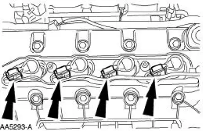
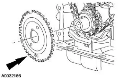
47. Remove the CKP sensor pulse wheel.
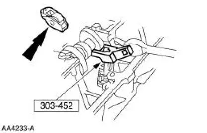
48. Using the special tool, remove the 32 roller followers.
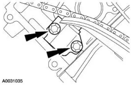
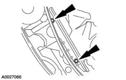
49. Remove the bolts and the RH and LH timing chain tensioners
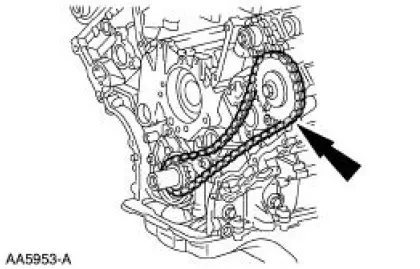
50. Remove the RH and LH timing chain tensioner arms.
51. Remove the RH and the LH timing chains and crankshaft sprocket.
52. Remove the RH and LH timing chain guides.
53. Remove the RH and LH cylinder heads.
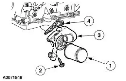
54. Remove the oil filter adapter.
1. Remove the oil filter.
2. Remove the bolts.
3. Remove the oil filter adapter.
4. Remove the gasket.
55. Clean and inspect the oil filter adapter.
- Flush the adapter with parts cleaner. If metal particles are present, install a new oil filter adapter.
56. Remove the bolts and the oil pump screen and pickup tube.

57. Remove the oil pump screen and pickup tube spacer.
58. Remove the nuts and the windage tray.
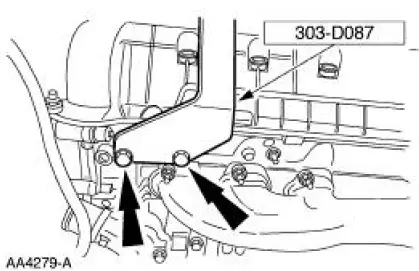
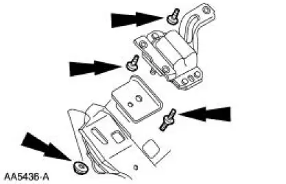
59. Remove the LH engine mount.
60. Remove the RH engine mount.
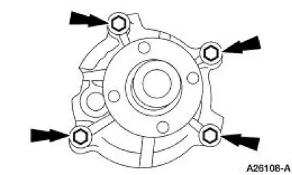
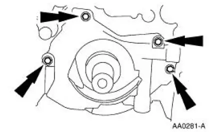
61. Remove the bolts and the oil pump.
62. CAUTION: Do not stamp the top of pistons, as ring land damage can occur.
NOTE: Connecting rods and rod caps should be numbered to keep the correct orientation in the following sequence.
Remove the connecting rod caps for piston number 1 and 6.
- Discard the bolts.
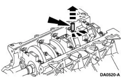
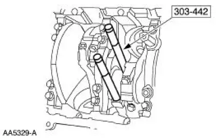
63. CAUTION: Do not scratch the cylinder walls or crankshaft journals with the connecting rod.
NOTE: Before removing pistons, inspect the top of the cylinder bores. If necessary, remove the ridge or carbon deposits from each cylinder using a cylinder ridge reamer following manufacturer's instructions.
Using the special tool, push pistons number 1 and 6 through the top of the cylinder block.
64. To remove pistons 3 and 5, 4 and 7, 2 and 8, turn crankshaft 90 degrees and repeat the previous two steps.
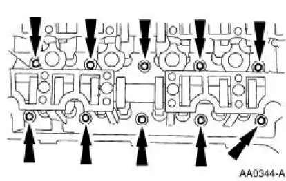
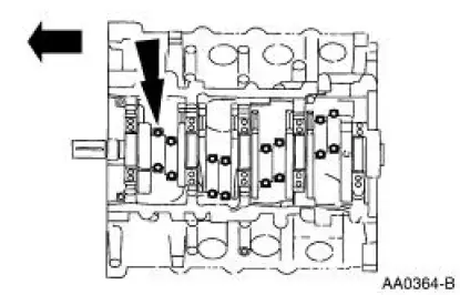
65. Remove the side main bearing cap bolts.
66. Remove and discard the main bearing cap bolts.
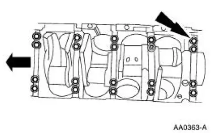
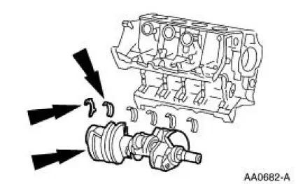
67. Remove the main bearing caps and the crankshaft lower main bearings from the cylinder block.
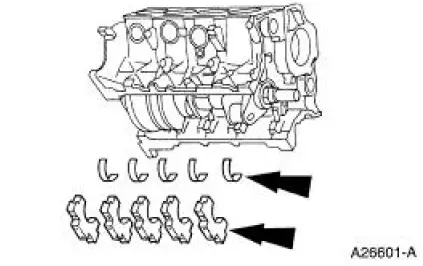
68. Remove the crankshaft, the crankshaft thrust washer, and the crankshaft upper main bearings from the cylinder block.
 Engine (Removal)
Special Tool(s)
Lifting Bracket, Engine
303-D087 (D93P-6001-A1)
Lifting Bracket, Engine
303-D088 (D93P-6001-A2)
Spreader Bar
303-D089 (D93P-6001-A3)
Rem ...
 Cylinder Head
Special Tool(s)
Compressor, Valve Spring
(Exhaust Side)
303-567 (T97P-6565-AH)
Compressor, Valve Spring
(Intake Side)
303-452 (T93P-6565-AR)
Holding Tool, ...
Other materials:
Flywheel Runout Check
Special Tool(s)
Dial Indicator/Magnetic Base
100-D002 (D78P-4201-B) or
equivalent
1. Mount the special tool so that the indicator contact point rides on the
clutch disc contact surface.
2. Turn the flywheel (6375); if the runout exceeds the ...
Removal
1. Disconnect the battery ground cable.
2. Remove the air cleaner outlet pipe.
3. Remove the radiator sight shield.
4. Remove the coolant recovery reservoir.
1. Disconnect the hose.
2. Remove the bolts.
3. Remove the coolant recovery reservoir ...
Intake Air Distribution and Filtering - Supercharger,
Charge Air Cooler
The supercharger (SC) is a positive displacement pump. Its purpose is to
supply an excess volume of
intake air to the engine by increasing air pressure and density in the
intake manifold. The supercharger
is matched to the engine by its displacement and ...
