Ford Mustang (1999-2004) Service Manual: Engine Dynamic Balance Shaft
Removal
1. Remove the timing chain (6268). For additional information, refer to Timing Chain in this section.
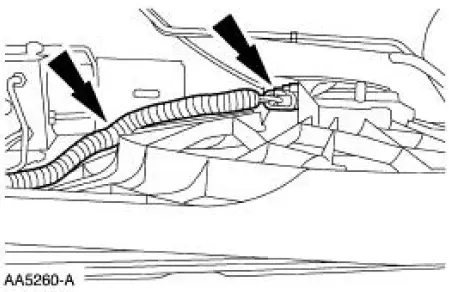
2. Disconnect and position the wire harness aside.
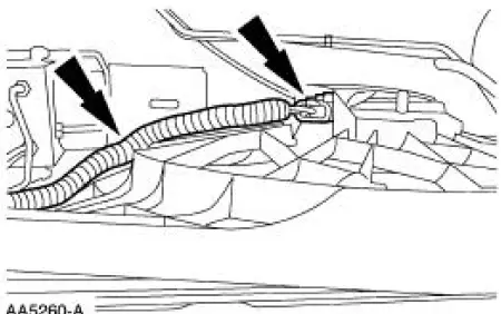
3. Remove the radiator fan and shroud assembly (8146).
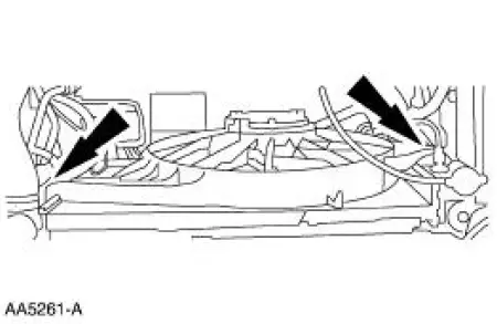
4. Remove the engine dynamic balance shaft (6A311).
- Remove the bolts.
- Remove the balance shaft driver gear, thrust plate and engine dynamic balance shaft as an assembly.
Installation
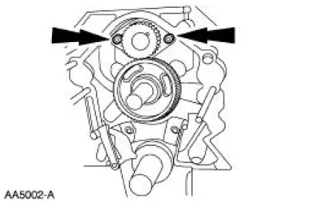
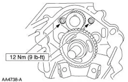
1. Turn the camshaft so that the timing mark is at 12 o'clock and install the engine dynamic balance shaft assembly into the cylinder block (6010). Turn the engine balance shaft driven gear so that the timing mark lines up with the timing mark on the engine balance shaft drive gear (6A303).
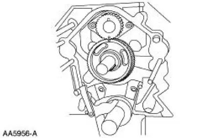
2. NOTE: If correctly aligned, the engine dynamic balance shaft keyway will be at 12 o'clock and the camshaft keyway will be at 6 o'clock on the camshaft.
Install the bolts.
3. Install the radiator fan and shroud assembly.
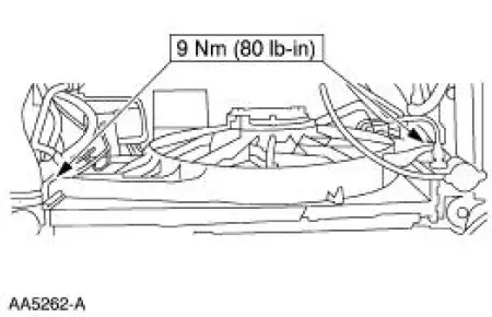
4. Connect the connector and install the pin-type retainer.
5. Install the timing chain. For additional information, refer to Timing Chain in this section.
 Camshaft
Material
Removal
1. Remove the valve tappets. For additional information, refer to Valve
Tappets in this section.
2. Remove the timing chain. For additional information, refer to Timing
Chain ...
 Timing Chain
Removal
1. Remove the timing cover. For additional information, refer to Engine
Front Cover in this section.
2. Remove the camshaft position sensor drive gear.
1. Remove the bolt.
2. Remov ...
Other materials:
Exhaust Manifold to Exhaust Gas Recirculation (EGR)
Valve Tube - Mach I
Removal
1. Remove the air intake scoop. For additional information, refer to
Section.
2. Disconnect the exhaust gas recirculation (EGR) tube from the EGR valve.
3. With the vehicle in NEUTRAL, position it on a hoist.
4. Disconnect the EGR tube from th ...
Piston - Ring End Gap
CAUTION: Use care when fitting piston rings to avoid possible damage to
the piston ring
or the cylinder bore.
CAUTION: Piston rings should not be transferred from one piston to another.
NOTE: Cylinder bore must be within specification for taper and
out-of ...
Emission control system
WARNING: Do not park, idle, or drive your vehicle in dry grass
or other dry ground cover. The emission system heats up the
engine compartment and exhaust system, which can start a fire.
WARNING: Exhaust leaks may result in entry of harmful and
potentially leth ...
