Ford Mustang (1999-2004) Service Manual: Timing Chain
Removal
1. Remove the timing cover. For additional information, refer to Engine Front Cover in this section.
2. Remove the camshaft position sensor drive gear.
1. Remove the bolt.
2. Remove the camshaft position sensor drive gear.
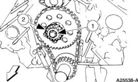
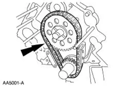
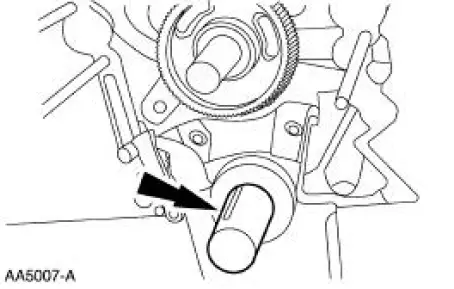
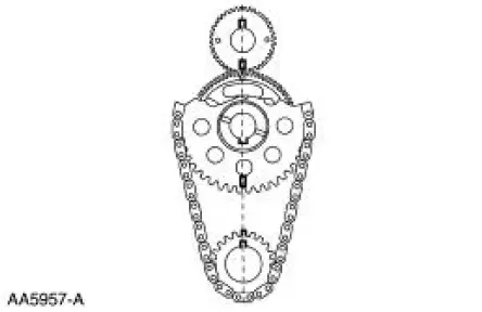
3. Rotate the crankshaft (6303) until the timing marks and keyways align.
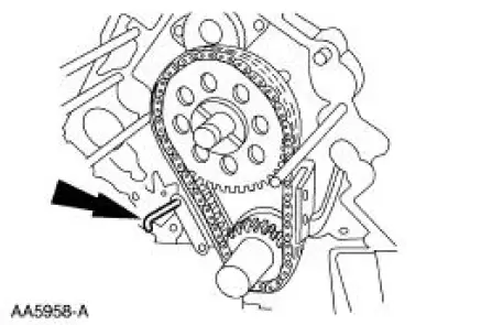
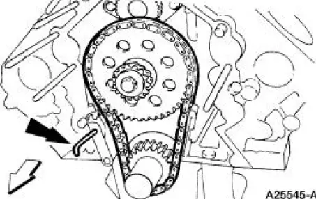
4. Compress and install a retaining pin to hold the timing chain tensioner (6L266).
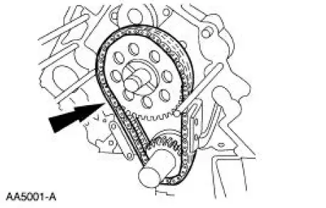
5. Remove the camshaft sprocket (6256), the crankshaft sprocket (6306) and the timing chain/belt (6268) as an assembly.
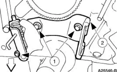
6. Remove the timing chain tensioner.
1. Remove the bolts.
2. Remove the timing chain tensioner.
Installation
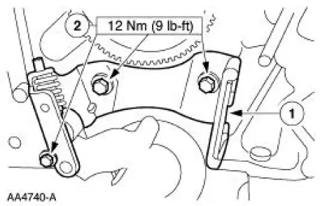
1. Install the timing chain tensioner.
1. Position the timing chain tensioner.
2. Install the bolts.
2. Rotate the crankshaft so the number one piston (6108) is at top dead center (TDC) and the key is at the 12 o'clock position.
3. If necessary, retract the tensioner pad retracting mechanism.
1. Compress the tensioner pad retracting mechanism.
2. Insert a retaining pin.
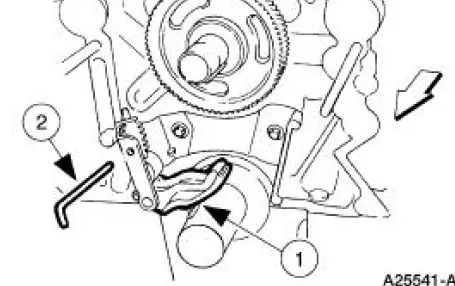
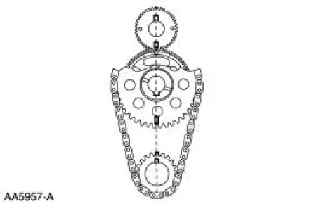
4. Turn the camshaft sprocket so that the timing mark is on the bottom of the balance shaft (6250).

5. Install the timing chain, the camshaft sprocket and the crankshaft sprocket.
6. Make sure that the timing marks and the keyways are aligned.
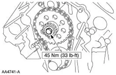
7. Install the camshaft position sensor drive gear.
8. Remove the retaining pin.
9. Install the engine front cover. For additional information, refer to Engine Front Cover in this section.
 Engine Dynamic Balance Shaft
Removal
1. Remove the timing chain (6268). For additional information, refer to
Timing Chain in this
section.
2. Disconnect and position the wire harness aside.
3. Remove the radiator fan and ...
 Exhaust Manifold - LH
Removal
1. Raise and support the vehicle. For additional information, refer to
Section.
2. Remove the LH exhaust manifold flange nuts.
3. Remove the RH exhaust manifold flange nuts.
4. Lower ...
Other materials:
Instrument Cluster (Diagnosis and Testing)
Refer to Wiring Diagrams Cell 60 , Instrument Cluster for schematic and
connector information.
Special Tool(s)
Worldwide Diagnostic System
(WDS)
418-F224,
New Generation STAR (NGS)
Tester
418-F052, or equivalent
diagnostic tool
...
Removal
WARNING: Always wear safety glasses when repairing an air bag
supplemental restraint
system (SRS) vehicle and when handling an air bag module. This will
reduce the risk of injury
in the event of an accidental deployment.
WARNING: Carry a live air ...
Removal
1. Disconnect the battery ground cable.
2. Remove the air cleaner outlet tube. For additional information, refer to
Section.
3. Remove the radiator sight shield.
4. Install the special tool.
5. Using the special tools, support the engine.
6. Raise and sup ...
