
Ford Mustang (1999-2004) Service Manual: Exhaust Manifold RH
Removal and Installation
1. Disconnect the battery negative cable. For additional information, refer to Section.
2. Remove the air cleaner outlet pipe. For additional information, refer to Section.
3. Disconnect the differential pressure feedback exhaust gas recirculation (EGR) system electrical and vacuum connections.
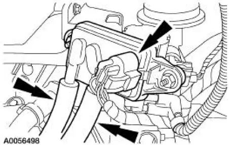
4. Disconnect the EGR tube.
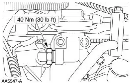
5. Remove the EGR tube.
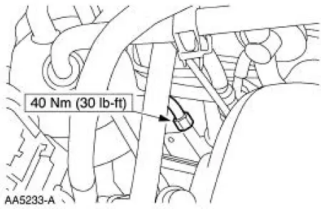
6. Raise and support the vehicle. For additional information, refer to Section.
7. Remove the LH exhaust manifold flange nuts.
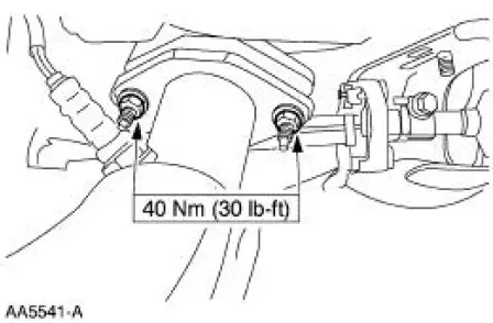
8. Remove the RH exhaust manifold flange nuts.
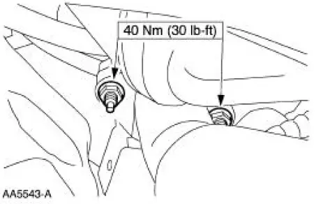
9. Lower the vehicle.
10. NOTE: Discard the exhaust manifold gasket.
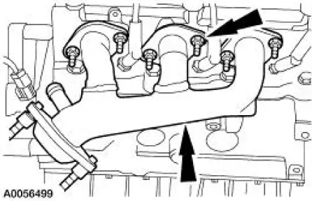
Remove the RH exhaust manifold retaining nuts and the RH exhaust manifold.
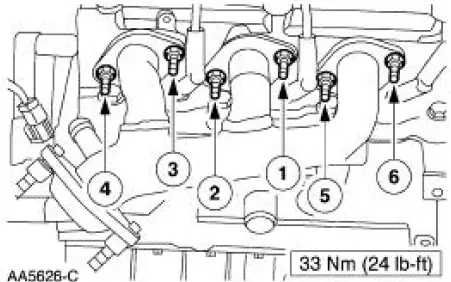
11. To install, reverse the removal procedure. Tighten the exhaust manifold nuts in the sequence shown.
 Exhaust Manifold - LH
Removal
1. Raise and support the vehicle. For additional information, refer to
Section.
2. Remove the LH exhaust manifold flange nuts.
3. Remove the RH exhaust manifold flange nuts.
4. Lower ...
 Cylinder Head LH
Special Tool(s)
Remover, Power Steering
Pump Pulley
211-016 (T69L-10300-B)
Installer, Power Steering Pump
Pulley
211-009
Material
...
Other materials:
Seat - Front Power
Removal and Installation
1. Remove the safety belt through the opening in the safety belt guide.
2. Move the seat forward.
3. Remove the bolt covers and remove the seat track bolts.
4. Move the seat rearward.
5. Remove the seat track nuts.
6. Move the ...
Accelerator Cable Bracket - Supercharged Engine
Removal and Installation
1. Disconnect the accelerator cable and speed control cable.
2. Depress the tabs and disconnect the accelerator cable and speed control
cable from the
accelerator cable bracket
3. Remove the bolts and the accelerator cable bracket ...
Vacuum Hose Repair - Mini-Tube
Special Tool(s)
Vacuum Pump Kit
416-D002 (D95L-7559-A) or
equivalent
1. Measure the length of the damaged area of the mini-tube vacuum hose.
2. Cut a piece of standard 1/8 inch inner diameter vacuum hose approximately 25
mm (1 inch
longer t ...
